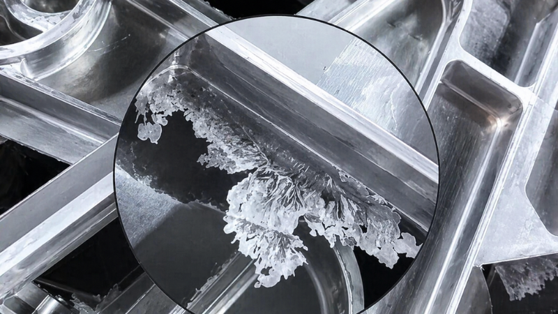
Flash in casting is a common defect that appears as thin excess metal along the parting line, slide interfaces, inserts, vents, or other die gaps. Although it may look like a simple trimming problem, casting flash can affect dimensional accuracy, sealing performance, die life, and production efficiency.
This article explains what flash in casting is, where it usually appears, and the main causes behind casting flashing, including insufficient clamping force, die wear, poor sealing, excessive injection pressure, and unstable temperature control. It also provides practical ways to reduce recurring flash through better machine setup, die maintenance, process adjustment, and thermal balance.
What Is Flash in Casting?
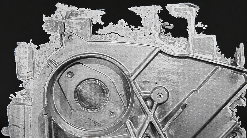
Flash in casting is the unwanted thin metal layer that appears outside the intended part geometry. It typically forms at:
- parting lines
- sliding cores or inserts
- die interfaces
- venting channels
- internal holes (often called “fin”)
The typical thickness of casting flash ranges from 0.05 mm to 0.30 mm. While a small amount of flash may sometimes help improve venting, excessive flash can:
- affect dimensional accuracy
- reduce part density and sealing performance
- cause leakage in pressure applications
- damage the die over time
The 6 Main Causes of Flash in Casting
Flash occurs when metal pressure exceeds the die’s sealing capability. This is usually the result of multiple combined factors.
1. Insufficient Clamping Force
If the machine clamping force is too low or improperly set, the die cannot remain fully closed under injection pressure. As a result, molten metal escapes through the parting line.
Incorrect projection area calculation can also lead to underestimating required clamping force.
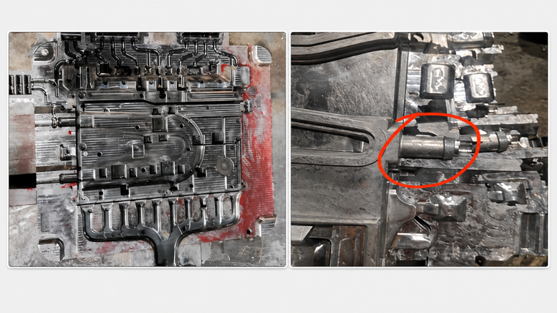
2. Die Mismatch and Wear
Flash often results from poor die sealing caused by:
- worn slides or inserts
- excessive clearance between components
- uneven or damaged parting surfaces
- die deformation under load
Even small gaps can allow high-pressure metal to penetrate and form flash.
3. Excessive Injection Pressure or Speed
High injection speed or unstable intensification pressure can create pressure spikes that exceed the machine’s clamping force.
This leads to:
- sudden die opening (die expansion)
- metal leakage at weak sealing areas
4. Thermal Expansion and Poor Temperature Control
Uneven heating or local hot spots can cause the die to expand unevenly, increasing the gap at the parting line.
Typical causes include:
- unstable die temperature
- insufficient cooling in thick sections or gate areas
- temperature fluctuation during production
5. Poor Machine Condition or Alignment
Machine-related issues can also contribute to flash:
- platen misalignment
- uneven tie-bar loading
- worn toggle or hydraulic systems
- improper die installation
These factors reduce the effective clamping force and sealing accuracy.
6. Contamination on Parting Surface
Foreign materials such as:
- residual aluminum
- debris
- lubricant buildup
on the parting line can prevent proper die closure and create leakage paths.
How to Reduce Flash in Casting
To reduce flash in casting, manufacturers should first check whether the machine has enough clamping force, whether the die closes properly, and whether injection pressure, speed, and temperature are within a stable process window.
1. Optimize Clamping Force
Ensure that clamping force is sufficient for the casting process.
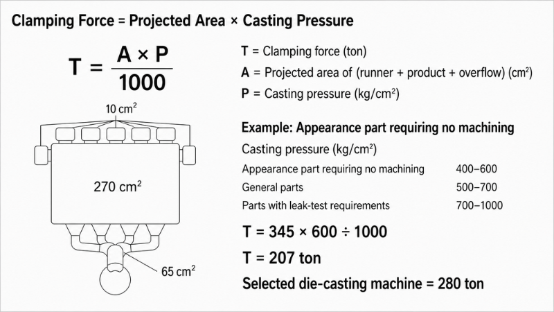
The basic calculation:
Clamping Force = Projection Area × Casting Pressure
When calculating projection area, include:
- part geometry
- runners and gates (+15–30%)
- overflow and vent systems (+10–20%)
Proper calculation helps prevent under-clamping.
2. Improve Die Sealing and Alignment
- repair worn parting surfaces
- reduce clearance between inserts and slides
- ensure flatness and parallelism
- clean parting surfaces before each cycle
Proper sealing is critical to prevent metal leakage.
3. Adjust Injection Parameters
- reduce excessive injection speed
- control intensification pressure rise
- avoid pressure spikes
- apply deceleration before filling completion
These adjustments help reduce impact force on the die.
4. Strengthen Die Structure
Improve die rigidity to prevent deformation:
- increase plate thickness
- add support pillars or backing plates
- reinforce large-span areas
A rigid die maintains better sealing under pressure.
5. Control Thermal Balance
- preheat the die before production
- maintain stable temperature during operation
- improve cooling in hot spots
- reduce temperature difference across the die
Stable thermal conditions reduce gap variation.
6. Maintain Machine Condition
- check tie-bar load balance
- verify platen parallelism
- inspect clamping system wear
- ensure proper die installation
Machine stability directly affects sealing performance.
Practical Troubleshooting Guide
Real Production Cases
A customer found two major issues during the production of a die-cast cooling plate: flash and leakage. Honjenny engineers reviewed the production data, machine tonnage, projected area, and simulation results to identify the root causes.
Issue 1: Flash
The customer used a 400-ton die casting machine. The projected casting area was 981.10 cm². Based on a safety factor of 1.1, the maximum allowable casting pressure was only 37 MPa.
However, after recalculating the effective projected area, including slide-related areas, and using a target casting pressure of 60 MPa with a safety factor of 1.2, Honjenny engineers found that the required clamping force was about 694 tons.
Conclusion:
The main cause of flash was insufficient clamping force. Poor die balancing and weak support strength also increased the risk. The most effective solution was to use a die casting machine with enough clamping force and verify machine tonnage before production.
Issue 2: Leakage
The same cooling plate also showed leakage during pressure testing. Continuous bubbles appeared from the lower-left corner of the part in water, indicating a sealing failure.
Honjenny engineers judged that the leakage was related to internal voids. Leak testing and X-ray inspection could confirm the defect, but they could not fully distinguish whether the voids were gas porosity or shrinkage porosity.
Further analysis showed that the area farther from the gate had higher air-entrapment risk. Based on gas-content prediction and flow simulation, Honjenny engineers concluded that gas porosity was more likely than shrinkage porosity.
Conclusion:
The leakage was mainly related to internal porosity risk, especially gas porosity near the sealing area. This gave the team a clear direction for later process optimization.
FAQs
What are types of casting defects?
Common casting defects include porosity, cold shut, cracks, soldering, flash, misrun, shrinkage, and surface defects.
How to make casting quality better?
Casting quality can be improved by controlling temperature, pressure, mold design, gating design, release agent use, die condition, and machine stability.
Which material is good for casting?
Good casting materials include aluminum, magnesium, zinc, cast iron, and steel. The best choice depends on part weight, strength, precision, cost, and application.
Conclusion
Flash in casting is not only a trimming issue. It can affect part dimensions, sealing performance, die life, and production stability.
In most cases, casting flash is caused by insufficient clamping force, poor die sealing, excessive injection pressure, die wear, or unstable temperature control. To reduce flash, manufacturers should check machine tonnage, projected area, die condition, process parameters, and thermal balance together.
A systematic review of these factors helps reduce casting flashing, improve part quality, and prevent repeated production problems.
Need Help Solving Flash Problems in Casting?
If you are experiencing recurring flash defects, send Honjenny your part drawings, machine tonnage, process parameters, and defect photos. Our engineering team can help identify the root cause and recommend practical solutions to improve casting quality and production efficiency.Contact us today to start your inquiry.
