Aluminum die casting defects are rarely isolated cosmetic problems. In production, recurring scrap, leak failure, coating instability, and dimensional inconsistency can often be traced back to a limited number of filling, venting, thermal, ejection, or die-condition issues.
In aluminum die casting, these defects commonly affect automotive housings, electronic enclosures, structural brackets, heat sinks, and other precision parts where surface quality, dimensional control, and repeatable process stability are critical. This article reviews nine common defect patterns from a practical troubleshooting perspective, covering their typical appearance, likely causes, inspection methods, product impact, and corrective actions.
If you are dealing with repeated die casting defects in production, the most important step is not simply identifying the visible symptom. The real value comes from linking defect location, morphology, and repeatability to the actual process condition behind it.
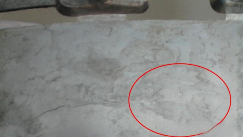
1. Discoloration/Spots
Defect phenomenon
Discoloration appears as uneven color, dark patches, oxidation marks, water-like stains, or irregular spots on the casting surface. It may reduce visual quality and interfere with painting, plating, or anodizing.
Core causes
- Release-agent residue: Excess spray volume or poor atomization leaves residue on the die surface, which can transfer to the casting and create visible staining.
- Oxidation contamination: Oxidized melt, soot, or carbonized residues can become trapped on the surface and produce dark spots or non-uniform appearance.
- Thermal imbalance: Local overheating or underheating changes the way the surface skin forms, making color variation more visible.
- Poor cavity cleanliness: Build-up on the cavity, slides, shot sleeve, or ladle can repeatedly imprint surface contamination onto the part.
Impact on the product
This defect primarily reduces cosmetic consistency and complicates painting, plating, or conversion coating. If the stained area is associated with contamination rather than simple discoloration, it can also lower surface-treatment yield and increase rework.
Diagnosis methods
Discoloration is usually identified by visual inspection, with attention to the location, distribution, and repeatability of the stained area. Diagnosis should then be correlated with spray condition, die-temperature records, and cavity cleanliness to determine whether the defect is caused by lubricant residue, oxidation, or local overheating.
Solution
- Reduce spray volume: Lower release-agent application to the minimum required for release and lubrication.
- Improve atomization: Adjust nozzle position, spray time, and spray pattern to avoid local pooling.
- Stabilize die temperature: Monitor critical die zones and eliminate persistent hot or cold spots.
- Clean contact surfaces: Remove deposits from the cavity, slides, shot sleeve, and transfer tools on a fixed schedule.
- Control melt cleanliness: Tighten skimming and handling practice to reduce oxide and soot transfer.
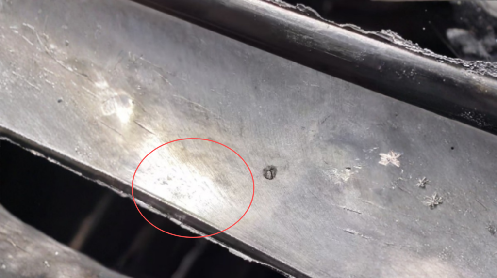
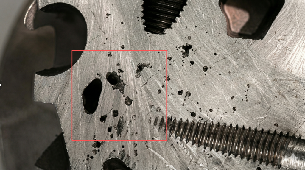
2. Drag Marks
Defect phenomenon
Drag marks appear as scratches, scuffing, smeared lines, or torn surface areas caused during die opening or ejection. In most cases, the defect is not random; it tends to recur in the same location because the local release condition is poor.
Core causes
- Insufficient draft: If the draft angle is too small, the casting drags against the die wall during release.
- Metal adhesion: Local sticking or soldering increases friction and causes the casting surface to tear during ejection.
- Rough die surface: Wear, poor polishing, or surface damage raises friction and promotes scuffing.
- Uneven ejection: Unbalanced ejector action or poor ejection timing causes localized rubbing and distortion.
- Local hot spots: Overheated areas are more prone to sticking, especially around deep pockets, ribs, and cores.
Impact on the product
Drag marks reduce surface quality immediately and can also affect fit, sealing surfaces, and visible cosmetic areas. When the defect is severe, it increases manual finishing, raises scrap, and often indicates a die-release problem that will continue until the local cause is corrected.
Diagnosis methods
Drag marks are typically diagnosed through visual inspection of their location, direction, and severity, followed by examination of the corresponding die area for insufficient draft, roughness, soldering, or uneven ejection. If the defect repeatedly appears in the same rib, core, or deep-wall area, the cause is usually a localized release problem.
Solution
- Increase draft: Recheck draft on deep walls, ribs, bosses, and core-contact zones.
- Restore die finish: Polish, repair, or recondition the affected cavity area.
- Optimize lubrication: Improve release-agent coverage in high-friction regions without over-spraying the entire die.
- Balance ejection: Verify ejector timing, stroke balance, and localized loading during release.
- Remove hot spots: Add local cooling or adjust cycle conditions where sticking repeats.
- Inspect for soldering: Check whether the surface damage is actually being initiated by aluminum build-up on the die.
3. Blisters
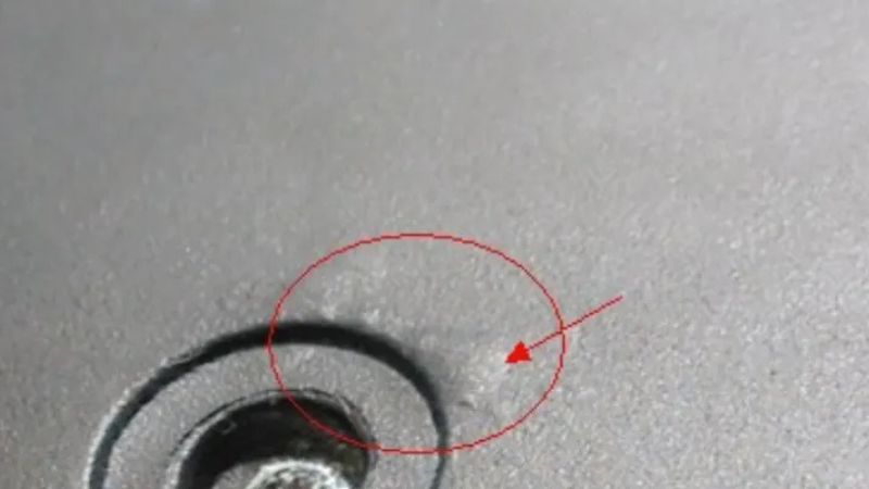
Defect phenomenon
Blisters are raised surface bubbles that often appear after coating, heating, impregnation, machining, or any later process that exposes the casting to temperature. The visible blister is usually the result of gas trapped just below the surface rather than a surface-only defect.
Core causes
- Subsurface gas: Gas porosity located near the skin expands during reheating and lifts the surface.
- Poor vent evacuation: Air trapped near the cavity end or in deep features remains close to the surface.
- Turbulent filling: Unstable flow folds air into the metal and leaves near-surface gas pockets.
- Excess moisture or spray residue: Water or release-agent residue can decompose or vaporize and increase local gas content.
Impact on the product
Blisters often escape detection in the as-cast condition and only become visible during coating or later thermal exposure. That makes them especially costly because they appear after value has already been added through machining or finishing.
Diagnosis methods
Blisters are usually confirmed by observing whether they appear after heating, coating, or other thermal exposure, and then verified by X-ray, CT, or sectioning to detect subsurface gas close to the casting skin. When the defect becomes visible only after baking or finishing, it is typically associated with near-surface trapped gas.
Solution
- Improve venting: Reassess vent layout, vent depth, and overflow effectiveness at the fill end.
- Stabilize vacuum: Confirm vacuum timing, sealing integrity, and actual evacuation performance under production conditions.
- Reduce turbulence: Modify gate geometry or fill pattern to avoid jetting and flow-front folding.
- Limit residual moisture: Reduce spray volume and ensure adequate evaporation before metal injection.
- Screen critical parts: Use X-ray or sectioning for parts that will be coated, baked, or require cosmetic stability.
4. Gas Porosity
Defect phenomenon
Gas porosity appears as smooth, rounded internal voids. It is often found by X-ray, CT, leak testing, or machining rather than visual inspection, which is why it remains one of the most expensive hidden defects in aluminum die casting.
Core causes
- Air entrapment: Air is drawn into the cavity by turbulent metal flow or unstable fill-front behavior.
- Insufficient venting: The cavity cannot evacuate air quickly enough during high-speed filling.
- Vacuum inefficiency: A vacuum system that leaks or switches too late does not materially reduce cavity gas.
- Spray-related gas generation: Excess die lube, moisture, or decomposition products add gas to the system.
- Shot instability: Incorrect sleeve fill, poor plunger behavior, or unstable stage transition promotes entrainment.
Impact on the product
Gas porosity reduces density, leak-tightness, and fatigue performance. It also creates secondary failures in machining, welding, impregnation, and coating, where hidden internal voids become exposed or act as leak paths.
Diagnosis methods
Gas porosity is mainly diagnosed by X-ray, CT, leak testing, or machining exposure, since it is often invisible on the external surface. The pore shape, location, and distribution should be reviewed together to determine whether the defect is related to air entrapment, poor venting, or ineffective vacuum performance.
Solution
- Rework vent paths: Increase vent effectiveness and confirm that trapped air has a real escape route.
- Tune vacuum timing: Make sure evacuation occurs before the metal front seals the vent path.
- Control fill behavior: Optimize gate position, gate area, and fill pattern to reduce entrainment.
- Stabilize shot profile: Correct first-stage, second-stage, and switchover consistency.
- Reduce wet conditions: Eliminate excess spray, standing liquid, and sleeve-side contamination.
- Verify internally: Use X-ray or CT on critical parts instead of relying on appearance alone.
5. Flow Marks / Surface Marks
Defect phenomenon
Flow marks appear as streaks, ripples, wave-like traces, or visible flow patterns on the casting surface. They are usually associated with the way the metal front travels through the cavity and freezes against the die surface. NADCA defines flow lines as marks indicating the manner of metal flow.
Core causes
- Unstable flow front: The advancing metal front loses uniformity in speed or temperature.
- Poor gate orientation: Metal enters the cavity in a way that produces uneven spread or localized impingement.
- Low local die temperature: Surface freezing begins too early and records the path of the flow front.
- Geometry interruption: Abrupt wall transitions, long thin paths, and sharp turns disturb metal flow.
Impact on the product
Flow marks are often treated as cosmetic, but they also indicate that filling is not fully controlled. In parts with thin walls or demanding appearance requirements, the same conditions that create flow marks may also increase the risk of cold shuts or incomplete fill.
Diagnosis methods
Flow marks are first identified by visual inspection of the surface pattern, flow direction, and affected area, and then evaluated against short-shot results or flow simulation to confirm unstable metal-front movement. If the marks follow the filling path, the defect is usually linked to gate layout, local die temperature, or interrupted flow behavior.
Solution
- Reposition the gate: Move or reshape the ingate so metal spreads more evenly across the cavity.
- Raise local temperature: Correct die-surface temperature in zones where the flow front is freezing too early.
- Adjust fill speed: Increase or rebalance velocity where the metal front is losing continuity.
- Smooth geometry transitions: Reduce abrupt thickness changes and sharp directional changes where possible.
- Validate with short shots: Use short-shot studies or simulation to confirm actual flow-front behavior.
6. Shrinkage Porosity
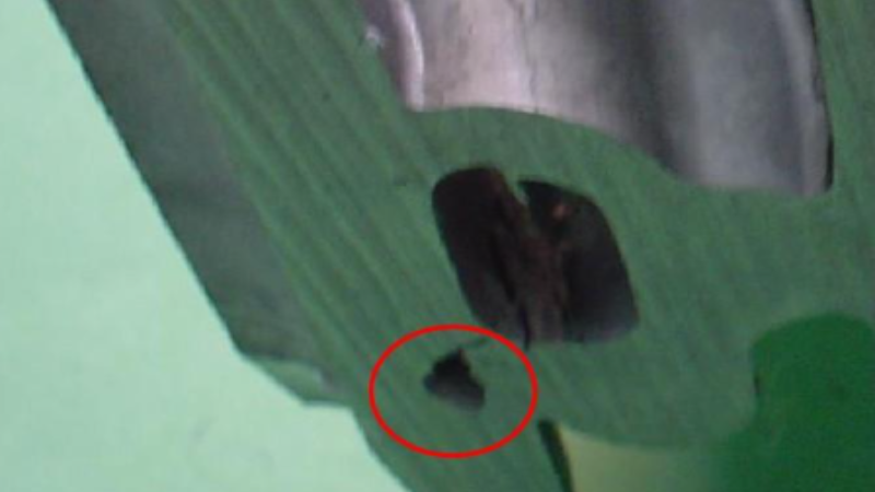
Defect phenomenon
Shrinkage porosity usually appears as irregular voids in thick sections, hot spots, or isolated masses of metal. It differs from gas porosity in both shape and mechanism: the problem is not trapped air, but the inability of the metal to compensate for volumetric contraction during solidification.
Core causes
- Thermal hot spots: Heavy sections solidify late and concentrate contraction in a small region.
- Insufficient feeding pressure: The gate freezes before pressure can effectively compensate for solidification shrinkage.
- Poor local cooling: Weak heat extraction causes non-uniform freeze behavior.
- Excess wall-thickness variation: Abrupt changes in section thickness create isolated shrinkage-prone zones.
Impact on the product
Shrinkage porosity reduces structural continuity and often becomes critical after machining, especially near threaded holes, bosses, and sealing faces. In load-bearing parts, it is more serious than a purely cosmetic defect because it directly affects local strength and reliability.
Diagnosis methods
Shrinkage porosity is typically confirmed by X-ray, CT, metallographic sectioning, or machining breakout, with particular focus on thick sections, hot spots, and sealing or threaded areas. Diagnosis should distinguish it from gas porosity, since shrinkage cavities are generally more irregular and strongly related to local solidification and feeding conditions.
Solution
- Reduce heavy sections: Core out thick masses and smooth wall-thickness transitions.
- Strengthen pressure transfer: Adjust intensification timing and maintain pressure before gate freeze-off.
- Improve local cooling: Add or optimize cooling near known thermal hot spots.
- Relocate the risk: Use overflow and feed-path strategy to move shrinkage away from functional areas.
- Confirm morphology: Use X-ray, CT, or sectioning to separate shrinkage from gas porosity before changing parameters.
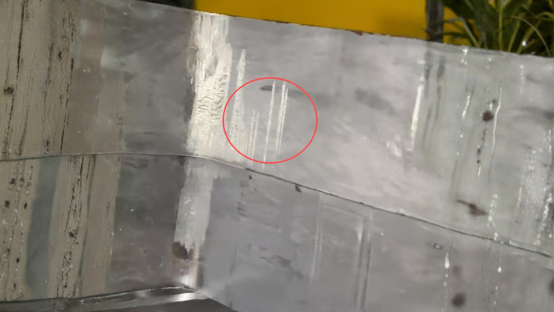
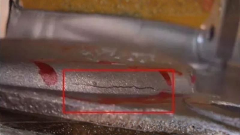
7. Cold Shuts
Defect phenomenon
A cold shut is a linear discontinuity formed when two metal fronts meet but do not fuse completely. It may look like a seam or shallow crack on the surface, but the root problem is incomplete metallurgical joining during fill.
Core causes
- Premature cooling: Metal fronts lose too much heat before they meet.
- Excessive fill time: The cavity takes too long to fill, allowing partial solidification before fusion.
- Low die temperature: A cold die extracts heat too quickly from the advancing metal.
- Insufficient fill energy: Shot speed or gate velocity is too low to sustain a coherent, hot flow front.
- Poor convergence location: Two fronts meet in a thin, cold, or remote part of the cavity.
Impact on the product
Cold shuts are not merely visual lines. They create local weakness, reduce pressure integrity, and can become initiation sites for cracking under vibration, fatigue, or impact loading.
Diagnosis methods
Cold shuts are usually detected by visual inspection as seam-like lines on the casting surface, and confirmed by dye penetrant testing or cross-section analysis if incomplete fusion is suspected. Short-shot evaluation and fill-path review are also useful for determining whether two metal fronts met in a low-temperature or weak-flow region.
Solution
- Increase die temperature: Bring critical fill zones into a stable operating window before injection.
- Shorten fill time: Adjust shot profile to reduce temperature loss before front convergence.
- Raise gate velocity: Increase flow energy where the metal front is stalling.
- Redesign convergence: Move the meeting point of metal fronts away from thin or low-temperature regions.
- Check with short shots: Verify where the fronts actually meet instead of assuming the simulated path is correct.
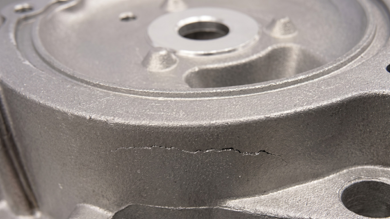
8. Cracks
Defect phenomenon
Cracks are open or partially open fractures in the casting. In aluminum die castings, they are commonly associated with contraction stress, constrained geometry, poor ejection conditions, or the presence of underlying defects such as porosity or cold shuts. NADCA specifically notes that alloy and process conditions affect resistance to cold cracks and to stresses from contraction during cooling.
Core causes
- Stress concentration: Sharp corners, deep ribs, and abrupt section changes concentrate tensile stress.
- Constrained contraction: The part cannot shrink freely during solidification and cooling.
- Early ejection: The casting is forced out before it has developed enough strength or thermal stability.
- Underlying discontinuities: Porosity, cold shuts, or shrinkage weaken the section and promote crack initiation.
- Thermal imbalance: Uneven cooling produces localized residual stress.
Impact on the product
Cracks directly compromise structural integrity. Even when the crack is fine, the part can lose pressure tightness, fatigue life, and impact resistance, and the defect often grows further during machining, assembly, or service loading.
Diagnosis methods
Cracks are commonly diagnosed by visual inspection and dye penetrant testing, with X-ray or fracture analysis used when internal discontinuities or stress-related initiation are suspected. If cracks consistently appear adt sharp corners, rib roots, boss transitions, or ejection zones, the cause is often related to stress concentration or constrained shrinkage.
Solution
- Add radii: Reduce stress concentration at corners, rib roots, and boss transitions.
- Balance cooling: Correct local thermal gradients that generate residual stress.
- Delay ejection: Allow the casting to gain sufficient strength before release.
- Inspect root defects: Check whether porosity or cold shuts are acting as crack initiators.
- Reduce constraint: Modify geometry or release conditions so the part can contract more uniformly.
9. Heat Checking
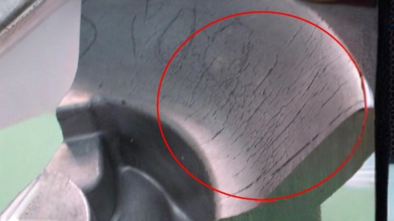
Defect phenomenon
Heat checking is a network of fine cracks that develops on the die surface due to repeated thermal cycling. Over time, these die-surface cracks transfer onto the casting as visible surface marks and eventually shorten die life. Thermal-fatigue studies on die-casting tools describe heat checking as one of the principal failure mechanisms in aluminum die-casting dies.
Core causes
- Thermal fatigue: Repeated heating and cooling cycles create cyclic stress in the die surface.
- Local overheating: Hot spots accelerate surface degradation and crack initiation.
- Uneven cooling: Large thermal gradients increase cyclic stress amplitude.
- Excess thermal shock: Aggressive spray on overheated die steel intensifies surface stress.
- Surface degradation: As the die surface softens or deteriorates, crack resistance falls further.
Impact on the product
Heat checking first damages the tool, then progressively degrades casting appearance and surface quality. Once the crack network deepens, maintenance frequency rises, die refurbishment becomes more frequent, and dimensional and cosmetic consistency become harder to maintain.
Diagnosis methods
Heat checking is diagnosed primarily on the die surface through magnified inspection, die-condition records, and comparison with recurring crack-like transfer patterns on the casting surface. When a fine crack network repeatedly develops in the same hot zone and begins to print onto the casting, the defect is typically caused by die thermal fatigue.
Solution
- Reduce thermal shock: Avoid heavy spray directly onto overheated die zones.
- Balance cooling: Improve cooling-channel layout and local heat removal at persistent hot spots.
- Control spray practice: Adjust spray time, direction, and coverage rather than using spray as a universal fix.
- Track die condition: Inspect heat-check growth routinely and repair early before the surface network becomes severe.
- Review cycle stability: Reduce avoidable thermal fluctuation caused by frequent interruptions or unstable operating windows.
FAQs
1. What is the difference between blisters and gas porosity?
Blisters are usually a surface deformation caused by subsurface gas expansion after reheating, while gas porosity refers to internal rounded voids trapped during filling or cavity evacuation failure.
2. How can shrinkage porosity be distinguished from gas porosity?
Shrinkage porosity is typically more irregular and forms in hot spots or thick sections, while gas porosity is smoother and rounder.
3. Why do drag marks keep appearing in the same location?
Because the root cause is often local: insufficient draft, poor polishing, die soldering, or a persistent hot spot in that cavity area.
4. Are flow marks only cosmetic?
Not always. Although often treated as a surface issue, they may indicate unstable filling, poor thermal balance, or improper gate design.
5. What causes cracks in die cast aluminum parts?
Cracks are usually linked to stress concentration, constrained shrinkage, poor ejection conditions, or weak material zones associated with internal defects.
Discuss Your Aluminum Die Casting Project with Honjenny
Honjenny provides aluminum die casting solutions with a focus on process stability, defect prevention, and consistent part quality. If you have a die casting project in development or need support with existing defect issues, send us your inquiry and our team will work with you to evaluate the technical requirements and manufacturing risks.
