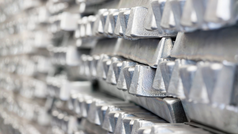
A crack in casting is a serious defect that can reduce part strength, sealing performance, and service reliability. Unlike minor surface defects, casting cracks may extend into the interior of the part and become the starting point of leakage, fracture, or long-term failure.
In die casting production, cracks can be caused by solidification shrinkage, thermal stress, improper part design, alloy composition, die misalignment, sticking, or mechanical force during ejection and trimming. Because different crack types have different root causes, identifying the crack pattern is the first step toward an effective solution.
This article explains the common types of casting cracks, how to identify them, what causes them, and how to reduce recurring casting crack problems in production.
What Is a Crack in Casting?
A casting crack is a narrow fracture where the metal matrix is partially or completely separated. It may appear on the surface or inside the casting.
Casting cracks can be:
- visible cracks that can be seen by the naked eye
- micro cracks that require magnification or microscopic inspection
- penetrating cracks that pass through the casting
- non-penetrating cracks that remain local or internal
Even small cracks should be treated seriously because they can grow under pressure, vibration, impact, or thermal cycling.
Main Types of Casting Cracks
Casting cracks are commonly divided into hot cracks, cold cracks, and mechanical tearing cracks.
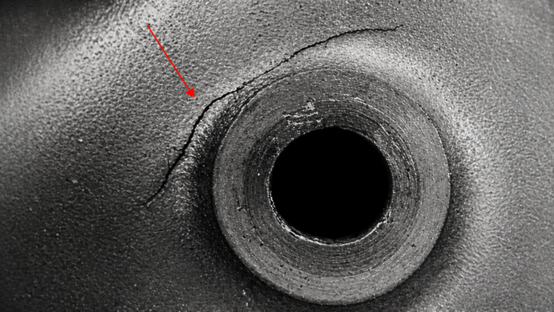
1. Hot Cracks
Hot cracks, also called solidification cracks, occur during solidification when the metal is still weak at high temperature and cannot withstand shrinkage stress.
Typical features:
- dark or oxidized crack surface
- irregular or curved crack path
- often follows grain boundaries
- may show dendritic structure
- often appears near hot spots, thick sections, or internal corners
Hot cracks are usually related to shrinkage, thermal stress, alloy behavior, or poor feeding during solidification.
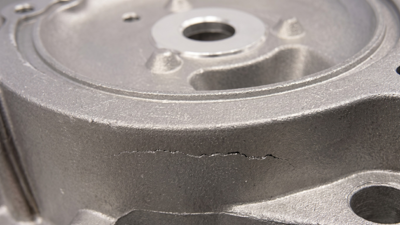
2. Cold Cracks
Cold cracks occur after the casting has solidified. They are usually caused by residual stress, external force, or mechanical loading.
Typical features:
- bright metallic crack surface
- little or no oxidation
- straighter and sharper crack shape
- may cut through grains
- often caused by ejection, trimming, handling, or constrained shrinkage
Cold cracks are common when the casting is pulled, pushed, twisted, or stressed after solidification.
3. Mechanical Tearing Cracks

Mechanical tearing cracks are caused by external mechanical force during mold opening, core pulling, ejection, or trimming.
They often appear when:
- the casting sticks to the die
- ejector force is not balanced
- the die shifts during opening
- sliders or cores are worn
- draft angle is too small
- the part is forced out of the die
Mechanical tearing cracks may appear near cores, deep cavities, thick sections, ejector areas, or locations with drag marks.
Crack Types and Typical Identification
Correct identification matters because a shrinkage-related crack and an ejection-related crack require different corrective actions.
Common Causes of Cracks in Casting
1. Solidification Shrinkage and Thermal Stress

During solidification, the casting shrinks. If shrinkage is blocked by the die, core, or part structure, stress can build up and cause cracks.
This often happens in:
- thick sections
- hot spots
- internal corners
- areas with sudden wall-thickness changes
- regions far from proper feeding or pressure compensation
Hot cracks are commonly linked to this type of stress.
2. Improper Part Design
Poor part geometry can increase stress concentration and restrict shrinkage.
Common design problems include:
- sharp corners
- small fillet radius
- sudden wall-thickness changes
- long straight ribs in round or frame-shaped structures
- thick isolated sections
- weak areas near bosses or deep cavities
These features can make the casting more likely to crack during cooling or ejection.
3. Alloy Composition Problems
Alloy chemistry affects crack sensitivity. If the alloy has poor ductility, high shrinkage tendency, wide solidification range, or harmful impurities, cracking risk increases.
For aluminum castings, the balance of elements such as Fe, Cu, and Si should be checked against the specified alloy standard. Improper composition, segregation, or ineffective silicon modification can reduce ductility and increase casting crack risk.
4. Excessive Pouring or Melt Temperature
If the melt temperature is too high, it can increase segregation, grain coarsening, oxidation, and shrinkage tendency.
This may increase the risk of hot cracks, especially in thick sections or areas with poor thermal balance.
5. Poor Die Temperature Control
Both high and low die temperature can contribute to cracking.
- A die or core that is too cold may increase cooling stress and cold cracking risk
- A local hot spot may increase shrinkage stress and hot cracking risk
Stable and balanced die temperature is more important than simply raising or lowering temperature.
6. Poor Filling or Incomplete Fusion
If metal fronts do not fuse properly, the casting may form weak areas such as cold shuts or weld-line defects. These weak zones can later develop into cracks under stress.
This is more likely to happen in areas far from the gate, thin-wall sections, or regions with poor flow continuity.
7. Die Misalignment During Opening or Closing
Die shift can introduce mechanical stress into the casting. If the moving die shifts downward or sideways during mold opening, the casting may be pulled or scratched by cores or die surfaces.
Signs may include:
- crack near core roots
- drag marks on hole walls
- cracks in thick-wall or core-bottom areas
- repeated crack in the same location
In this case, the crack is not only a material issue. It is also a die alignment and machine setup issue.
8. Uneven Ejection Force
Cracks can occur when the casting is not pushed out evenly.
Typical causes include:
- unbalanced ejector layout
- ejector pins with inconsistent length
- insufficient ejector area
- sticking or soldering in local areas
- worn sliders or cores
- poor guided ejection
If the casting tilts, twists, or sticks during ejection, mechanical tearing cracks can appear.
9. Trimming and Deburring Stress
Cracks may also be generated during trimming, flash removal, or deburring, especially when the part already has internal stress or weak sections.
Poor trimming die condition, excessive cutting force, or improper support can create local cracking.
How to Prevent Casting Cracks
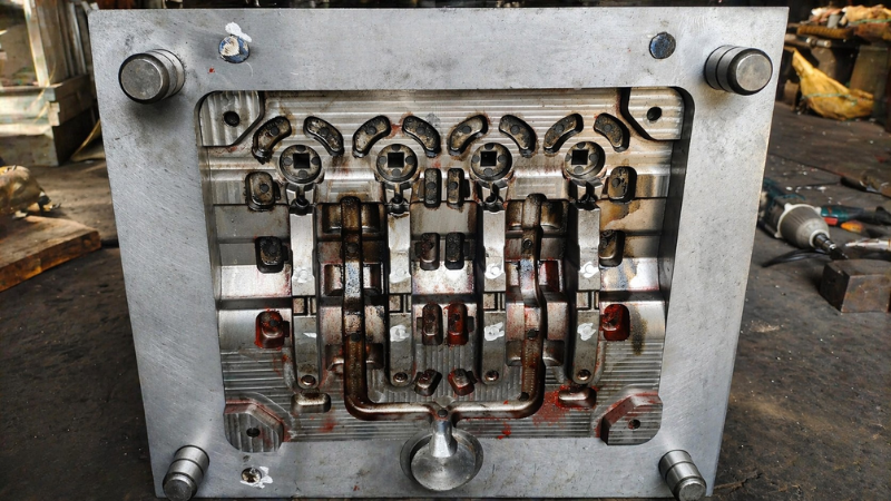
1. Improve Part Design
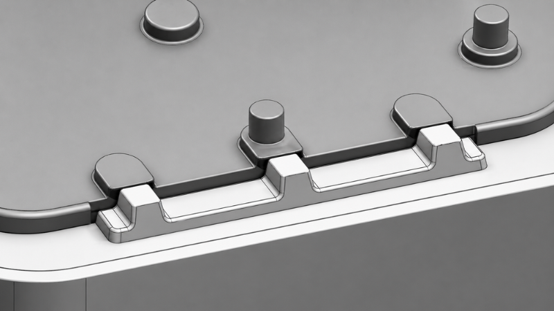
Good design reduces stress concentration and shrinkage restriction.
Recommended actions:
- increase fillet radius
- avoid sharp internal corners
- reduce sudden wall-thickness changes
- optimize rib design
- avoid heavy isolated sections
- improve transition areas near bosses and deep cavities
As shown in the figure; no law can be used in the same type of cavity to move the local active area, and the local temperature can be matched, reducing the heat pressure. The model wall thickness can be increased evenly, and the model temperature difference can be created by reducing the wall thickness difference.
2. Optimize Thermal Control
Balanced thermal control helps reduce both hot cracks and cold cracks.
Recommended actions:
- improve cooling near hot spots
- reduce excessive temperature differences
- control die and core temperature
- avoid extreme local overheating or overcooling
- adjust pouring temperature within the approved process window
For shrinkage-related cracks, cooling and pressure compensation should be evaluated together.
3. Control Alloy Composition
Check whether the alloy composition meets the required standard.
For aluminum castings, pay attention to:
- Fe level
- Cu level
- Si level
- impurity control
- segregation risk
- silicon modification effectiveness
If cracks repeat under stable process conditions, alloy composition should be reviewed.
4. Improve Gating and Filling
Poor filling can create weak metal-front junctions that later crack.
Recommended actions:
- optimize gate location
- improve metal flow direction
- avoid severe turbulence
- reduce cold shut risk
- strengthen feeding or pressure transfer in hot spots
If cracks appear near the gate or in distant thin-wall areas, flow behavior should be checked.
5. Improve Mold Opening and Ejection Stability
For cracks caused by mechanical stress, ejection must be smooth, straight, and balanced.
Recommended actions:
- ensure straight and guided ejection
- balance ejector force across the casting
- inspect ejector pins for height difference
- check for sticking, soldering, or drag marks
- confirm sliders and cores work smoothly
- avoid shaking or tilting during ejection
If cracks occur during ejection, first check whether the part is being pushed out evenly or pulled by local sticking.
6. Check Die Alignment and Machine Condition
Die shift or poor machine condition can create repeated mechanical cracks.
Recommended actions:
- observe die opening and closing movement
- check whether the moving die shifts during separation
- verify tie-bar loading and platen alignment
- inspect guide pins and bushings
- reinstall or realign the die if needed
- check support blocks under the moving platen
- repair worn connection parts if necessary
If crack marks appear together with pulling or rubbing marks, die alignment should be checked early.
7. Reduce Sticking and Release Resistance
Sticking increases mechanical force during ejection.
Recommended actions:
- improve draft angle
- polish local die surfaces
- inspect soldering or adhesion areas
- improve release agent coverage
- check deep cores and hidden spray areas
- repair worn sliders or cores
For cracks near cores or deep cavities, release resistance is often a key factor.
8. Optimize Holding and Ejection Timing
Holding time, cooling time, and ejection timing should be adjusted based on part structure and defect type.
For some cracks, excessive holding or delayed ejection may increase shrinkage stress. For others, early ejection may cause deformation or tearing. The correct setting depends on the part geometry, wall thickness, gate design, and thermal balance.
FAQs
Can a small casting crack be repaired?
Small cracks may be repairable in some non-critical parts, but cracks in pressure-tight, structural, or safety-related castings should usually be rejected because they can grow during use.
How do you inspect cracks in casting?
Common inspection methods include visual inspection, dye penetrant testing, X-ray inspection, CT scanning, and metallographic sectioning, depending on crack size and location.
Are casting cracks always visible on the surface?
No. Some cracks are internal or microscopic and cannot be seen by the naked eye. They may only be found through X-ray, CT, pressure testing, or sectioning.
Conclusion
Casting cracks can come from shrinkage, thermal stress, poor part design, alloy problems, die misalignment, uneven ejection, or trimming force. Because different cracks have different causes, the first step is to identify whether the defect is a hot crack, cold crack, or mechanical tearing crack.
To prevent recurring casting cracks, manufacturers should review the part design, alloy composition, die temperature, filling behavior, mold alignment, and ejection stability together. A systematic check helps find the real root cause and improve casting strength, sealing performance, and production reliability.
Need Help Solving Casting Crack Problems?
If you are experiencing crack defects in casting, send Honjenny your part drawing, alloy type, process parameters, defect photos, and inspection results. Our engineering team can help identify whether the crack is caused by shrinkage, thermal stress, mechanical force, die alignment, or ejection problems.Contact Honjenny today to start your inquiry.
