
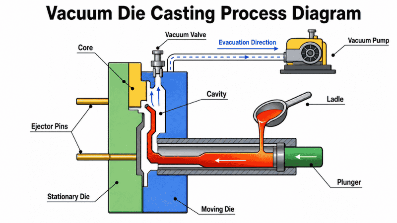
Vacuum die casting is used when conventional high-pressure die casting cannot provide stable internal quality for sealed, thin-walled, welded, or heat-treated parts. The process removes air from the die cavity before and during metal injection, reducing the gas available to form pores.
In one Honjenny ADC12 housing project, this change raised the leak-test pass rate from 62% to 96%–98%. However, a vacuum system cannot compensate for blocked air paths or poor gating. This guide explains how the process works, where it helps, and what must be controlled before production.
What Is Vacuum Die Casting?
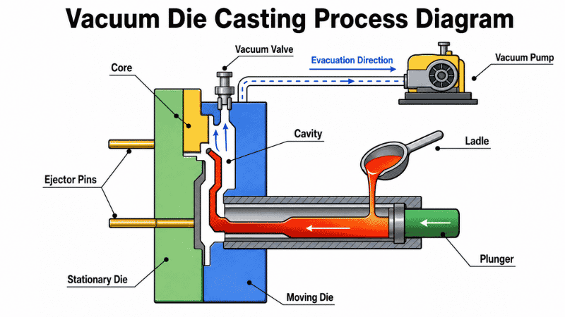
Vacuum die casting is a variation of high-pressure die casting (HPDC). Molten metal still enters a reusable steel die at high speed and pressure, but a pump evacuates air and process gases from the shot sleeve and die cavity before the cavity fills.
Conventional HPDC relies mainly on vents and overflows as incoming metal pushes air out. If the metal closes those routes too early, air becomes trapped. Vacuum removes much of it before enclosure.
“Vacuum assist” may describe localized suction, while high-vacuum die casting uses a sealed die and controlled evacuation throughout filling. The North American Die Casting Association describes high vacuum as cavity pressure below 50 mbar. Terms such as HVDC and UHVDC matter less than the vacuum curve, die sealing, and finished-part results.
Vacuum Die Casting vs. Vacuum Casting
Vacuum die casting and vacuum casting are not the same manufacturing process. The standard vacuum casting process normally uses silicone molds to produce polyurethane prototypes in small quantities. Vacuum die casting instead removes air from a reusable steel die before molten metal is injected under high pressure.
The search phrase vacuum casting metal can refer to vacuum die casting, vacuum investment casting, or melting and pouring metal under vacuum. When molten metal is injected into an evacuated steel die under high pressure, vacuum die casting is the more accurate term.
How Does Vacuum Die Casting Work?
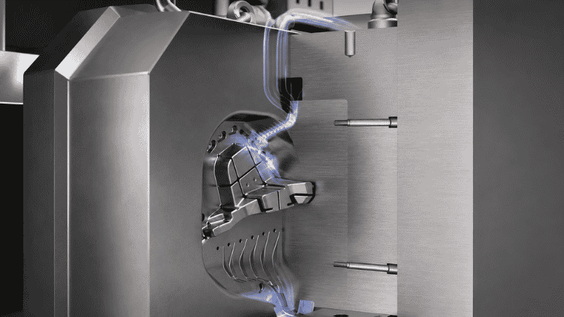
The process follows the main stages of conventional HPDC, with cavity evacuation added to the shot sequence.
1. Prepare and Seal the Die
The die is cleaned, sprayed, closed, and clamped. The parting line, slides, ejector pins, shot sleeve, channels, and valve connections must be sealed. Pump capacity cannot compensate for air leaking through these interfaces.
2. Evacuate the Shot Sleeve and Die Cavity
The vacuum valve opens after the die closes and before high-speed filling. The pump draws air, lubricant vapor, steam, and other gases through channels connected to the cavity.
The slow-shot profile must provide enough time to reach the target vacuum before metal enters the cavity. An ADC12 study found that insufficient evacuation time allowed metal to arrive too early. Casting density also increased as cavity pressure decreased under the tested conditions.
3. Inject Molten Metal Under High Pressure
The plunger forces the alloy through the runner and gates while the system evacuates gas ahead of the flow front. A vacuum valve or chill block prevents metal from entering the vacuum line.
4. Solidify and Eject the Casting
Pressure is maintained while the casting solidifies. The die opens, ejector pins release the part, and runners, overflows, and flash are trimmed before inspection or secondary processing.
Equipment and Die Design Requirements
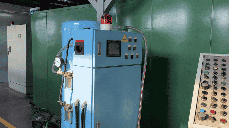
A practical system includes a pump, reservoir, filters, sensors, valves, channels, and a sealed die. H13 steel is commonly used for die components, with local treatments selected for wear conditions.
The vacuum port should connect to the actual last-filled region, not simply the point farthest from the gate. Flow simulation identifies separated flow fronts, premature vent closure, and trapped-air zones. CAD and casting simulation then guide die, gate, vent, and vacuum-channel design.
Vents, overflows, and vacuum channels must form a continuous route to the outlet. Fondarex also identifies die tightness, lubrication, thermal control, shot-sleeve sealing, alloy, and machine parameters as quality factors.
Shop-Floor Case: Why Maximum Vacuum Failed on a 1.2 mm Housing
Honjenny reviewed a 5G filter housing with a minimum wall thickness of 1.2 mm and many enclosed rib cells. One-sided gating created a long filling route, and the closed ribs divided the cavity into isolated air pockets. The main vacuum port connected only to the parting-line vent.
Mold-flow analysis predicted trapped air, but the customer requested a trial first. Although the system reached its vacuum setting, the ribs showed incomplete filling and dense pores. The defect rate approached 40%.
The tooling and part design were then revised in four places:
- Each rib received a 0.2 mm process opening to connect the separated air paths.
- Two-sided symmetrical gating shortened the filling distance.
- Overflows and vents were moved to the actual filling endpoints.
- Needle-type vacuum valves were added in the most serious trapped-air regions.
After the changes, the thin walls filled completely, pores in the original problem areas were largely eliminated, and the production defect rate remained below 5%.
The lesson is direct: a vacuum can remove only the air that can reach a vacuum outlet. Increasing pump capacity does not solve an internally blocked evacuation path.
Suitable Alloys and Part Design
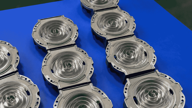
Vacuum-assisted systems can process aluminum, magnesium, and zinc alloys. Aluminum suits structural and sealed housings, magnesium reduces mass, and zinc suits smaller detailed parts.
Lower gas content can improve heat-treatment and welding potential, but the alloy still controls compatibility. Vacuum does not make ADC12 suitable for every heat-treatment schedule or guarantee a sound weld.
What Does Aluminum Vacuum Casting Mean?
Aluminum vacuum casting is a broad term that may describe more than one process. In this article, the relevant process is vacuum-assisted aluminum HPDC, in which the die cavity is evacuated before molten aluminum enters under pressure. It is different from silicone-mold vacuum casting and vacuum investment casting.
Design rules remain project-specific:
- Wall thickness: Keep it uniform. Minimum thickness depends on alloy fluidity, flow length, gate position, die temperature, and machine capacity. The 1.2 mm case is not a universal minimum.
- Draft and radii: Provide sufficient draft and replace sharp internal corners with radii.
- Ribs and bosses: Avoid heavy intersections and isolated rib grids. Connect enclosed features to vents or overflows.
- Machining allowance: Keep sealing faces and critical bores away from predicted pore clusters.
NADCA likewise recommends uniform walls, draft, fillets, controlled flow, and an escape route for cavity air. High vacuum does not replace these basics.
Advantages of Vacuum Die Casting
Compared with conventional HPDC, a correctly designed vacuum process can provide several practical benefits:
- Lower gas porosity: Less cavity air is available to become trapped in the metal.
- Better leak performance: Fewer connected pores reduce leakage paths in coolant, oil, pneumatic, and sealed electronic housings.
- More consistent properties: Removing large gas pores reduces local weak sections and batch variation.
- Better response to heating: Lower gas content reduces blistering during compatible heat treatment or coating bake cycles.
- Improved filling: Lower cavity back pressure helps thin walls and detailed regions fill more consistently.
- Lower scrap: Reduced rejection, impregnation, machining loss, and coating failure can offset the added process cost.
Production Case: ADC12 EV Charger Water-Cooling Housing
An ADC12 water-cooled housing for an electric vehicle onboard charger initially ran with conventional HPDC. At a 0.5 MPa leak-test pressure, only 62% of the parts passed. Leakage appeared at several water-channel locations and became worse after thermal cycling.
Full leak testing separated the failures. Sectioning and X-ray inspection then found round, smooth pores concentrated near the filling endpoints. The pores were not located in thick thermal hot spots, so the team ruled out shrinkage as the main mechanism and identified filling-related gas entrapment.
After conversion to vacuum die casting, the leak-test pass rate stabilized at 96%–98%. The internal pore-area ratio decreased from 0.8% to below 0.15%, while porosity-related scrap fell from 28% to about 3%. Blistering during the powder-coating bake cycle also disappeared.
The improvement depended on matching evacuation timing and venting to the filling pattern, then verifying the change through leak testing, X-ray, and destructive analysis.
Limitations: What Vacuum Cannot Fix
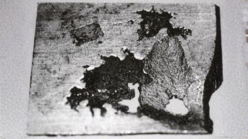
Vacuum die casting mainly addresses gas entrapment. It does not automatically eliminate shrinkage porosity, oxide films, inclusions, cold shuts, soldering, or distortion.
Gas pores are commonly rounded and smooth. Shrinkage cavities are irregular and usually occur at hot spots or last-solidifying sections. Gas problems may require better air paths and less turbulent filling; shrinkage may require thermal balancing, local pressure, geometry changes, or feeding control. Our porosity in casting guide explains the distinction.
The system also adds cost and maintenance. Seals wear, filters collect residue, channels become restricted, and valves can close at the wrong time. The pump’s rated vacuum is therefore not a sufficient acceptance criterion.
Quality Control for Vacuum Die Cast Parts
Process control should connect each shot to a measurable result. Useful records include cavity vacuum over time, tank vacuum, valve response, filter condition, and leakage alarms. The full curve shows whether evacuation occurred before filling.
Finished-part inspection must match the failure risk:
- 2D X-ray locates major internal density differences during sampling or production.
- Industrial CT shows three-dimensional pore position and volume. ZEISS notes that CT separates density and thickness effects better than one 2D radiograph.
- Sectioning and metallography reveal pore shape and defect type.
- Leak testing verifies the function of sealed housings and fluid channels.
- Thermal cycling and bake tests reveal leakage or blistering after heating.
X-ray may show a pore without confirming a leak path, while leak testing cannot locate the defect. Use both process data and part inspection.
Typical Applications
Typical applications include:
- EV charger and inverter housings
- Battery and powertrain parts
- Welded automotive structures
- Pump and valve bodies
- 5G filter housings
- Outdoor telecom enclosures
- Heat sinks
- Thin-walled electronic housings
Post-Processing and Tolerances
Vacuum control does not replace CNC machining, heat treatment, or finishing. Because machining can expose subsurface pores, leak-test critical housings afterward and confirm dimensions after all machining, heating, and coating operations.
Vacuum Die Casting vs. Other Manufacturing Options
CNC machining and 3D printing can check fit and assembly before tooling. Validating filling, vacuum performance, and porosity requires casting simulation and representative trial tooling.
When Should You Choose Vacuum Die Casting?
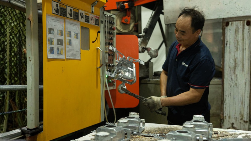
Choose vacuum die casting when gas porosity affects:
- Leak testing
- Welding
- Heat treatment
- Thin-wall filling
- Mechanical property consistency
- Coating bake performance
Conventional HPDC may remain sufficient when limited internal porosity does not affect function, machining, or appearance.
The process makes economic sense when repeat demand can amortize the die and conventional HPDC creates unacceptable quality costs. No universal minimum volume applies. Evaluate part size, cavity count, tool life, inspection, scrap risk, machining, and annual demand together.
Information Required for Project Review
For an RFQ, provide:
- 2D drawings and 3D CAD files
- Required alloy
- Estimated annual volume
- Critical dimensions and tolerances
- Leak-test pressure and acceptance criteria
- Heat-treatment or welding requirements
- Surface-finishing requirements
- Internal-quality and inspection standards
These details determine whether conventional HPDC, localized vacuum assist, or a fully sealed high-vacuum process is appropriate.
Conclusion
Vacuum die casting is valuable when trapped gas limits sealing, thin-wall filling, mechanical consistency, or downstream heating. Its success depends on an open evacuation path, correct port placement, sealed tooling, synchronized shot control, and inspection tied to the part’s function.
Before specifying the process, identify the defect mechanism and define measurable acceptance criteria. A higher vacuum reading alone does not guarantee a better casting.
Start Your Vacuum Die Casting Project With Honjenny
Honjenny supports custom aluminum die casting and zinc die casting from DFM and tooling through production, secondary CNC machining, surface finishing, and inspection. Send your CAD files, material, annual quantity, leak-test standard, and finishing requirements through our contact page to request an engineering review and quotation.