
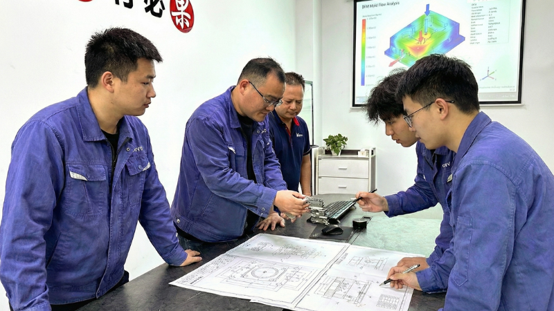
Optimizing aluminum casting design directly determines structural weight, dimensional tolerance, thermal performance, and manufacturing cost in high-pressure industrial applications. Unoptimized CAD geometry leads to extended cycle times, severe gas porosity, and premature tooling failure.
This guide details 14 critical engineering rules for design for casting. By controlling parameters such as draft angles, wall thickness transitions, and machining allowances, mechanical engineers can mitigate common casting defects and ensure B2B manufacturing feasibility for aluminum die cast parts.
The Importance of DFM in Aluminum Die Casting
Design for Manufacturing (DFM) is the critical analytical phase that bridges a theoretical CAD model and actual high-pressure die casting (HPDC) production. Executing DFM protocols directly determines manufacturing feasibility, structural integrity, and long-term production yield.
Skipping DFM analysis inevitably leads to extended trialout phases (T1/T2), severe casting defects, and costly tooling modifications.
- Tooling Longevity: Unoptimized geometries with sharp internal corners or inadequate draft angles cause severe thermal fatigue. This mechanical stress on the H13 tool steel leads to premature die failure through craze cracking (heat checking).
- Defect Mitigation: Proactive DFM identifies thermal nodes and isolated heavy masses. This allows engineers to core out sections or add structural ribs before the tool is cut, eliminating the root causes of internal shrinkage voids and gas porosity.
- Machining Optimization: DFM ensures the casting geometry provides a highly rigid baseline for secondary CNC operations. By controlling mass and preventing structural deflection, the cast part can reliably achieve precision post-machining tolerances as tight as ±0.005mm.
- Cycle Time Reduction: Uniform wall thicknesses and strategically placed pockets accelerate heat dissipation. This reduces the in-die solidification time, maximizing production throughput and lowering the final unit cost.
14 Point Aluminum Casting Design Guide
1. Material Selection: Specifying Alloys Based on Performance Criteria
Component geometry and manufacturing feasibility are fundamentally dictated by alloy selection. Each material presents specific manufacturing constraints, meaning optimization requires precise alloy specification aligned with structural requirements.
Alloying elements dictate critical mechanical and thermal properties, including fluidity, ultimate tensile strength, electrical conductivity, and solidification ranges. However, not all aluminum grades possess the fluidity or hot-tear resistance required for high-pressure die casting (HPDC).
Common HPDC aluminum alloys include:
- A380: Offers a baseline balance of metal fluidity and structural strength.
- A383 (ADC12): Features higher silicon content for improved hot-tear resistance and complex die filling.
- A413: Provides excellent pressure tightness and castability for intricate geometries.
Engineers must balance mechanical performance requirements against budget constraints and tooling longevity when specifying an alloy for volume production.
2. Draft Angles and Ejection Mechanics
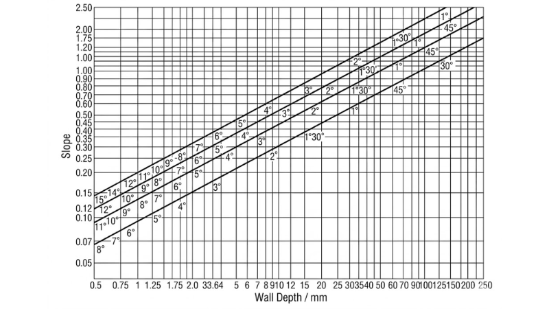
Draft is a critical parameter in aluminum die casting design. It is defined as the taper or incline applied to part cores and surfaces that sit perpendicular to the die’s parting line.
Engineers must specify adequate draft to ensure manufacturing feasibility. Without sufficient draft angles, the solidifying aluminum will shrink and seize onto the tool steel. This leads to difficult ejection, severe surface galling on the component, and potential catastrophic damage to the die or ejector pins.
Engineering Considerations for Draft Design
When calculating draft angles, engineers must evaluate the following constraints:
- Baseline Specifications: Standard geometric features typically adhere to universally accepted baseline draft angles.
- Internal vs. External Draft: Internal walls and cored surfaces generally require twice the draft angle of external walls. This compensates for the high friction created as the aluminum shrinks tightly onto the internal die cores during the cooling phase.
- Alloy-Specific Shrinkage: Draft requirements fluctuate based on the specific volumetric shrinkage rate of the selected aluminum alloy. Engineers must calculate final draft tolerances according to the specific material grade being cast.
3. Moving vs. Fixed Die Considerations

The mating interface between the moving die (ejector half) and the fixed die (cover half) must be precise. The fixed die is structurally simple, but the moving die is highly complex because it houses dynamic components like core sliders.
Core Shift and Dimensional Risks During injection, extreme molten metal pressure can force internal core sliders to shift outward. This mechanical deflection results in oversized cast dimensions.
To manage this shift, tolerances for moving components are calculated using two factors:
- Linear Tolerance: The overall length of the core slider.
- Projected Area: The surface of the slider directly exposed to the high-pressure metal.
Because injection pressure naturally pushes components apart, moving die features typically yield positive (oversized) tolerances. Engineers should minimize these tolerances as much as structurally possible and reference NADCA guidelines for standard and precision limits based on the projected
4. Parting Line Dynamics and Tolerances
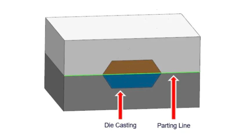
The parting line is the unavoidable mating boundary between the fixed and moving die halves. During injection, extreme hydrostatic pressure pushes the die halves apart. This microscopic separation causes molten aluminum to escape, forming flash that requires secondary trimming operations.
Parting Line Tolerances Operational tolerance defines the maximum allowable die separation during injection. Because internal cavity pressure always fights the machine’s clamping force, actual separation is always a positive value.
This tolerance is calculated based on:
- Projected Area: The primary variable driving separation force along the parting plane.
- Alloy and Dimensions: Specific material shrinkage and draw depths affect limits.
- Tonnage Constraints: Components with a projected area exceeding 300 in² (1935.5 cm²) require engineering review to verify machine clamping feasibility.
5. CNC Machining Allowances
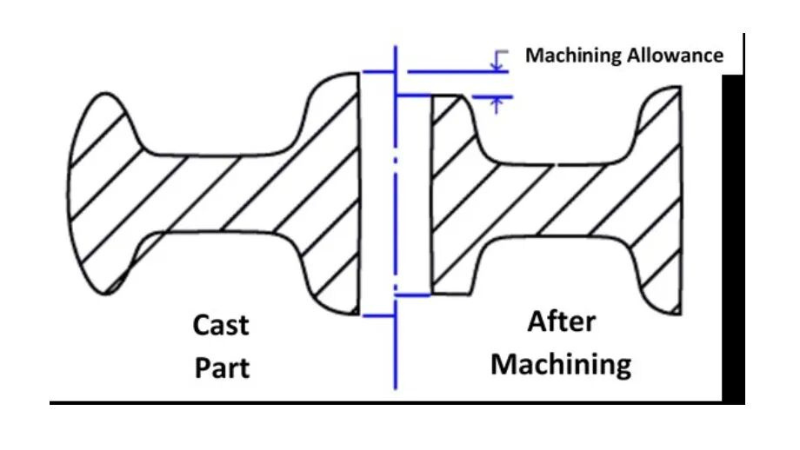
Machining allowance defines the material volume designated for removal during secondary operations. As-cast surfaces exhibit inherent roughness and minor geometric deviations that require CNC machining to achieve precision tolerances.
Engineers must tightly control material removal to protect the casting skin. The highest density and mechanical strength in a die-cast part exist within this rapidly solidified outer layer.
- Porosity Exposure: Removing excessive material breaches the dense casting skin. This exposes internal gas porosity and compromises structural integrity or flat sealing surfaces.
- Minimum Allowance: The recommended baseline allowance is 0.2 mm. This depth cleans surface imperfections while minimizing cutting tool wear.
- Maximum Allowance: The maximum allowable material removal is calculated by adding the expected casting deformation value to the 0.2 mm baseline.
- Large Flat Geometries: Large-area components are highly susceptible to thermal warpage. These features require custom allowance calculations verified during the DFM phase.
6. Wall Thickness and Solidification Control
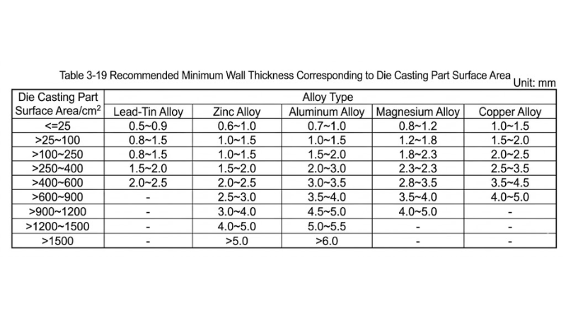
Maintaining uniform wall thickness is mandatory. Consistent thickness ensures unobstructed molten metal flow and uniform cooling rates, which prevents internal shrinkage defects.
Key Design Constraints:
- Gradual Transitions: If thickness variations are structurally necessary, use radii or fillets to transition smoothly. Abrupt changes cause flow turbulence.
- Eliminate Sharp Edges: Sharp internal corners restrict metal flow and cause ejection drag. Sharp edges are only acceptable directly along the parting line.
- Structural Optimization: To increase part stiffness, do not simply increase wall thickness (which causes porosity and slow cooling). Instead, integrate reinforcing ribs to add rigidity without adding excessive mass.
Standard Thickness Parameters:
- Typical Range: 2.0 mm to 3.5 mm for standard structural components.
- Thin-Wall Limits: Small, specialized parts can achieve walls down to 0.7 mm.
- Out-of-Bounds Designs: Geometries requiring extreme thickness deviations mandate early DFM consultation to verify manufacturing feasibility.
7. Lightweight Design: Optimizing Ribs and Pockets
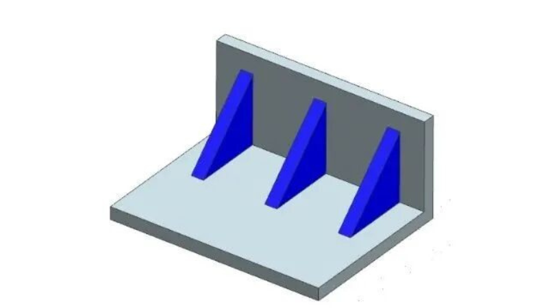
Integrating ribs and pockets (recesses) allows engineers to significantly reduce material volume and component weight without compromising structural integrity.
Rib Design Constraints Ribs add required bending stiffness while enabling the removal of unnecessary solid mass. When specifying ribs for aluminum die cast parts, adhere to the following parameters:
- Apply Generous Radii: Never use sharp edges on ribs. Sharp edges act as severe stress concentrators and increase fracture risk. Always apply a minimum fillet radius of 1.524 mm (0.060″).
- Maintain Uniform Thickness: Keep the rib’s wall thickness consistent with the surrounding nominal wall. This ensures uniform cooling and prevents internal shrinkage voids.
- Maximize Draft Angles: Apply the largest allowable draft angle to all rib surfaces to prevent the component from sticking to the die during ejection.
Pocket (Recess) Design Pockets core out excess material from non-load-bearing areas, which reduces weight and accelerates the thermal cooling cycle. However, unsupported pockets can induce irregular volumetric shrinkage.
- Add Reinforcing Ribs: To stabilize the pocket and prevent structural distortion, integrate supporting ribs around its perimeter.
- Optimize Metal Flow: Strategically placing ribs around a pocket not only increases rigidity but also provides favorable flow paths for the molten aluminum during the high-pressure injection phase.
8. Structural Ribs and Rigidity
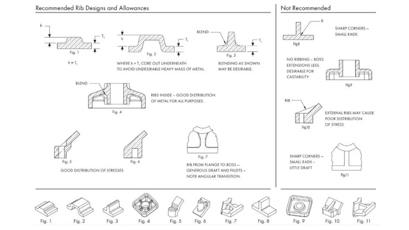
Ribs increase bending stiffness and reinforce weak areas, such as thin walls. They provide significantly higher strength than solid, thick sections, which are highly susceptible to internal gas porosity.
- Stress Management: Overusing ribs can cause stress concentrations along the rib edges.
- Lightweighting: To minimize material volume and component weight, ribs are frequently designed around hollow sections (metal-saving pockets).
9. Hole and Edge Distance Clearances
Placing cored holes too close to the part perimeter creates structurally weak cross-sections.
- Minimum Clearances: Engineers must maintain calculated minimum clearances between the hole and the part edge and between adjacent holes based on the hole diameter. This prevents extreme stress concentrations.
- Machining Alternative: If the design cannot accommodate sufficient cast clearance, designate the holes for secondary CNC machining.
10. Managing Holes and Slots
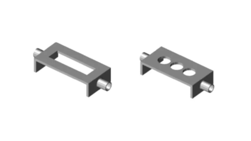
Heavy concentrations of holes and slots (common in electronic enclosures) severely disrupt molten metal flow and complicate ejection due to solidification shrinkage.
- Maximize Draft: Enclosed flat surfaces inside holes and slots require significantly larger draft angles to ensure clean ejection.
- Flow Bridges: Use bridge-like features across openings to maintain continuous metal flow paths.
- Avoid Long Slots: Long, continuous slots completely obstruct metal flow. When possible, replace them with a series of smaller, continuous cored holes.
11. Thread Casting Constraints
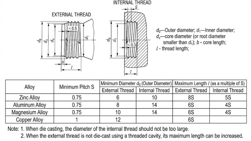
- External Threads: Can be cast using conventional HPDC equipment by aligning the thread axis with the parting line or utilizing simple sliders. To accommodate minor die shifts, design an unthreaded flat section along the parting line rather than full-diameter threads.
- Internal Threads: Casting internal threads requires expensive, complex rotating core mechanisms. For production speed and economy, internal threads are almost exclusively created via secondary CNC tapping.
- Precision Fits: Cast threads cannot achieve precision-grade fits. Specify direct geometric tolerances for the die components, and rely on secondary machining if strict thread tolerances are required.
12. Cast-in Inserts
When the aluminum alloy cannot withstand localized high-stress loads, solid inserts (e.g., steel threaded helicoils or bronze bearings) are placed directly into the mold cavity before injection.
- Applications: Ideal for high-wear bearing points, frequently assembled threads, or concentrated tensile loads.
- Tolerance Requirements: Inserts require exceptionally tight dimensional tolerances. Oversized inserts will crush and permanently damage the H13 tool steel. Always verify insert specifications with the foundry.
- Stress Management: Analyze thermal stresses caused by the insert, ensure sufficient anchoring features, and avoid sharp corners that cause localized stress.
13. Notches and Grooves (T-Slots and Dovetails)

Notches (through-slots) and surface grooves are typically designed as clamping elements or clearance openings for mating components.
- Spacing Constraints: Avoid clustering notches tightly together, as this compromises part integrity and metal flow.
- Edge Radii: Never leave perfectly sharp edges in flat-bottom or V-shaped grooves. Round all internal and external edges to prevent surface defects and minimize secondary electroplating/coating costs.
14. Eliminating Sharp Edges

Sharp 90-degree corners are highly detrimental in die casting design.
- Thermal Hot Spots: Sharp corners create thermal nodes that concentrate shrinkage stresses, leading to material defects and structural weakness.
- Tooling Cost: Achieving a true zero-radius internal edge requires highly expensive, zero-tolerance EDM machining on the tool steel, which is practically impossible to maintain.
- Mitigation: Always apply fillets, radii, or chamfers to all internal and external corners. The only acceptable location for a sharp edge is directly along the parting line to ensure the die halves seal perfectly.
FAQs
What is the minimum machining allowance for aluminum die castings?
The recommended minimum machining allowance is 0.2 mm. This depth successfully cleans up surface imperfections while preventing the cutting tool from breaching the dense casting skin and exposing internal porosity.
Why are internal threads not cast in aluminum parts?
Casting internal threads requires a specialized rotating core inside the die, heavily inflating tooling costs and extending cycle times. It is much faster and more cost-effective to cut internal threads using secondary CNC tapping.
Why do die cast parts need draft angles?
Draft is a slight taper applied to vertical walls. As aluminum cools, it shrinks and tightly grips the internal steel die cores. Draft angles reduce friction, allowing the part to eject smoothly without scoring the surface.
How do thick walls cause defects in die casting?
Excessively thick walls cool significantly slower than surrounding thin sections. This delayed solidification isolates molten pools inside the part, which contract as they freeze, forming severe internal shrinkage voids.
Conclusion
A successful aluminum casting design is an exercise in balancing structural intent with fluid dynamics and thermal constraints. By systematically applying these 14 engineering parameters specifically optimizing wall thickness transitions, maximizing draft angles, and controlling CNC machining allowances mechanical engineers can effectively protect the casting skin and mitigate internal porosity.
Thorough DFM optimization during the CAD phase directly prevents premature tooling failure, reduces the need for mold modifications, and ensures stable, high-yield volume production.
Contact Honjenny Engineering
Need Help Optimizing Your Aluminum Casting Design?
If you want to ensure the manufacturing feasibility of your CAD geometry and prevent defects like porosity before production begins, send Honjenny your 3D/2D drawings, alloy type, and production requirements. Our engineering team will conduct a thorough DFM analysis to recommend practical structural optimizations that improve part quality, manufacturability, and production stability. Contact us today to start your inquiry.