In structural design and industrial manufacturing, dealing with sharp corners is a critical engineering step. Leaving corners sharp can lead to severe stress concentration, rapid tool wear, and poor material flow during manufacturing processes. To solve this, engineers rely on two standard features: fillets and chamfers.
While they serve similar basic functions, removing sharp edges to improve safety and manufacturability, their geometric profiles and structural impacts are fundamentally different. Drawing on 30 years of manufacturing experience, this guide breaks down the technical differences in fillet engineering, how a chamfer bevel functions, and how to choose the right feature for your next die casting or machining project.
What is a Fillet in Engineering?
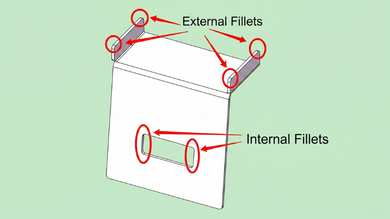
A fillet is a rounded corner or edge on a manufactured part. In mechanical design, fillets can be applied to both internal and external corners.
In fillet engineering, the primary objective is to distribute mechanical stress over a broader surface area. By eliminating the sharp transition between two intersecting planes, a fillet significantly reduces stress concentration factors (Kt).
This makes the component far more resistant to fatigue failure under high-load conditions. In processes like die casting, internal fillets are heavily utilized to facilitate smooth molten metal flow and prevent shrinkage cracks during the cooling phase.
What is a Chamfer?
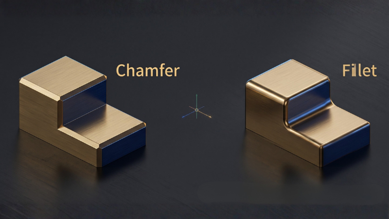
A chamfer is a sloped or angled edge that connects two intersecting surfaces. Unlike the smooth curve of a fillet, a chamfer creates a flat, transitional plane, most commonly set at a 45-degree angle.
When discussing a chamfer bevel or comparing a bevel and chamfer, it is important to note a slight distinction: a bevel typically spans the entire thickness of a part’s edge, whereas a chamfer is only a partial cut to break a specific sharp corner.
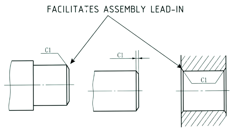
Chamfers are primarily used to ease the assembly of mating parts, such as guiding a pin into a hole or inserting a fastener, serving as an effective lead-in feature.
Fillet vs Chamfer: Key Engineering Differences
To understand chamfer vs fillet, we must evaluate them across geometry, stress distribution, and manufacturing efficiency. The table below outlines the core technical distinctions.
Advantages and Limitations of Fillets
When designing for industrial manufacturing, applying fillets offers significant structural benefits, though it is not a universal solution for every edge.
Advantages:
- Enhanced Structural Integrity: Dissipates stress across a continuous radius, preventing premature part failure.
- Optimized Metal Flow: In die casting, generous internal fillets allow aluminum or zinc alloys to flow smoothly into the mold cavity, minimizing gas porosity.
- Extended Tooling Life: Reduces thermal fatigue and wear on mold cores. (Note: At Honjenny, our precision tooling serves strictly as an internal support for our die casting production, ensuring optimal fillet implementation without external tooling constraints.)
Limitations:
- Mating Interference: A large fillet can interfere with the assembly of a square-edged mating component.
- Machining Time: In CNC operations, internal fillets require specific ball-end mills and longer cycle times compared to straightforward chamfering.
Advantages and Limitations of Chamfers
A chamfer bevel provides distinct advantages when structural load is not the primary concern, particularly during post-processing and assembly.
Advantages:
- Assembly Efficiency: Acts as a guide for inserting bolts, pins, or interlocking components, reducing assembly friction.
- Cost-Effective Machining: Easily cut using standard spot drills or chamfer mills in CNC processes, requiring less time and tool changes than fillets.
- Safe Handling: Effectively deburrs sharp edges to protect workers and end-users from injury.
Limitations:
- Lower Fatigue Resistance: The distinct corners created by a chamfer still accumulate more stress than a smooth fillet radius.
- Poor Coating Adhesion: Sharp transitions at the edges of a chamfer can cause issues like edge-pulling during powder coating or painting.
Critical Factors for Choosing Between a Fillet and Chamfer
Evaluating a fillet vs chamfer goes beyond simple geometry. Engineers must weigh multiple technical factors to ensure the part meets performance and budget requirements.
Machining Time and Efficiency
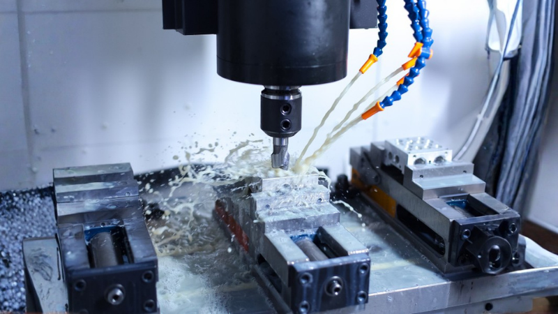
In CNC machining, time directly dictates efficiency. Creating an internal fillet often requires specialized ball-end mills and slower 3D profiling paths. This extends the overall cycle time.
Conversely, cutting a chamfer bevel is highly efficient. A standard spot drill or chamfer mill can execute a straight-angled cut in a rapid, single-pass operation, dramatically reducing machine time.
Manufacturing Cost Analysis
Because machining time is lower, a chamfer is generally much cheaper to produce subtractively than a fillet. The tooling required for chamfers is universal and adaptable to various depths.
Fillet engineering, particularly on internal pockets, requires specific tool radii. If a design features multiple different fillet sizes, the CNC machine must perform multiple tool changes, further driving up production costs.
Stress Distribution and Load Bearing
Sharp corners generate a high Stress Concentration Factor (Kt). A fillet uses a continuous radius to distribute this mechanical stress over a broad surface area, effectively minimizing (Kt).
While a chamfer removes the extreme 90-degree corner, it still leaves two distinct obtuse vertices. These vertices can accumulate stress, making fillets the superior choice for high-load or vibration-heavy structural components.
Surface Treatment and Coating Adhesion
Sharp edges cause “edge-pulling” during powder coating or painting, where liquid pulls away from the corner due to surface tension. This leaves a microscopic thin spot, exposing the bare metal to rapid rust and corrosion.
Proper fillet engineering creates a smooth curve that allows coatings to adhere uniformly. If corrosion resistance is a priority for your component, a rounded fillet outperforms a straight chamfer.
Aesthetics and Ergonomic Safety
Both features effectively remove dangerous burrs, protecting operators during handling and assembly. However, they offer different cosmetic finishes.
A smooth fillet provides a premium, streamlined appearance often preferred in visible consumer-facing components. A chamfer provides a sharp, industrial look that is highly functional for mechanical assemblies.
Engineering Applications: When to Use Which?
Choosing between a bevel and chamfer or a fillet depends entirely on where the feature is located and how the part interacts with other components.
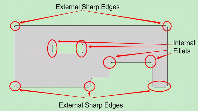
Outside Edges vs. Inside Corners
For outside edges (boundaries), a chamfer is usually sufficient to prevent injury and reduce machining costs.
For inside corners (pockets and cavities), a fillet is almost always required. CNC milling cutters are cylindrical and naturally leave a radius in internal corners; attempting a sharp internal chamfer is physically impossible without specialized processes like EDM.
Holes, Screws, and Threading Preparations
When preparing tapped holes or designing insertion points for screws, a chamfer is the undisputed standard.
A well-placed chamfer bevel acts as a lead-in, guiding the fastener smoothly into the thread. It also allows countersunk screw heads to sit perfectly flush with the component surface.
Mating Parts and Assemblies
In assemblies, chamfers are ideal for male mating components (like shafts or pins), guiding them easily into receiving holes.
However, if an internal corner has a large fillet, a mating part with a perfectly square edge will not sit flush. In these cases, the mating part must feature an even larger chamfer to clear the fillet and ensure proper alignment.
Industry-Specific Design Preferences
Different manufacturing processes dictate entirely different design rules. What works for CNC machining may cause defects in net-shape manufacturing.
Design Preferences for Die Casting
21-1024x576.jpg)
In die casting, generous fillets are not optional, they are an engineering necessity. Molten aluminum and zinc flow laminarly around rounded fillets, preventing turbulence, trapped air, and gas porosity.
Furthermore, fillets eliminate thermal hot spots in the mold. At Honjenny, mold production is strictly an auxiliary service; we build molds only when a customer has a die-casting requirement. We engineer our internal mold designs with optimized fillets to prevent thermal fatigue and ensure a long tooling lifespan.
Design Preferences for CNC Machining
In subtractive CNC machining, designers prefer chamfers on all external edges to keep costs down. A single chamfer tool can rapidly run along the entire outer toolpath.
When internal fillets are unavoidable in CNC, engineers prefer to use the largest radius possible. A larger radius allows the machinist to use a thicker, more rigid end mill, reducing tool deflection and speeding up material removal.
FAQs
Can I use a bevel and chamfer on the same part?
Yes. Engineers often use a chamfer on the edges of a drilled hole to allow a screw head to sit flush, while using a bevel on the outer edge of a thick plate to prepare it for welding.
Does a fillet affect die casting mold design?
Absolutely. Proper fillet engineering is standard practice in die casting mold design. It prevents thermal hot spots in the steel mold and ensures the cast part ejects smoothly without dragging or cracking.
Conclusion
Ultimately, the decision between a fillet vs chamfer comes down to balancing structural integrity with manufacturing efficiency. Proper fillet engineering is essential for high-load components, minimizing stress concentration, and ensuring optimal material flow in net-shape processes like die casting.
Conversely, a chamfer bevel is the superior choice for reducing CNC machining costs, preparing threaded holes, and facilitating smooth mating assemblies. By carefully evaluating the specific application and chosen manufacturing method, engineers can apply the correct edge treatment to maximize both part performance and production viability.
Optimize Your Component Design with Honjenny
Properly applying a chamfer vs fillet is just one step in optimizing a component for mass production. With over 30 years of manufacturing expertise, Honjenny specializes in translating complex engineering designs into high-performance aluminum and zinc die-cast parts. Our in-house tooling capabilities are dedicated entirely to supporting your die casting projects, ensuring that every radius, draft angle, and chamfer is perfectly executed for optimal production efficiency.
Contact us engineering team today to review your CAD models and ensure your next project is optimized for strength, assembly, and cost-effective manufacturing.
