Only a handful number of modern manufacturing processes are as productive as CNC milling. The highly versatile method harnesses the combined power of computerized precision with mechanical efficiency.
However, CNC milling doesn’t exactly correspond to an individual method. It’s more like a category with distinctive variants of the milling machine. And each machine type suits specific application scenarios.
What is a CNC Milling Machine?
A CNC milling machine is a highly advanced metal/material cutting tool. The computer-controlled tool cuts and shapes solid materials with extreme precision.
The “CNC” stands for Computer Numerical Control. It means the machine’s (cutter) movements are entirely directed by software.
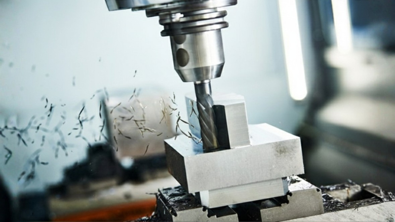
Milling involves a rotating cutter that removes material from a solid block to create a desired shape. Think of it as a sculptor’s chisel, guided by exact digital instructions.
What Makes CNC Milling Important for Manufacturers and Production Engineers?
- Prototyping: Engineers can quickly test new designs by milling prototypes directly from CAD models. It reduces development cycles and speeds up innovation.
- Precision Engineering: CNC milling ensures tolerances as tight as ±0.01 mm. Such machining precision is critical in industries like aerospace, automotive, and medical devices.
- Mass Production: CNC milling can replicate parts thousands of times with consistent quality. It makes a validated design perfect for highly scaling production.
The global CNC machine market valued over $80B in 2023. It’s projected to surpass $120B by 2030 due to demand for automation and precision manufacturing.
Key Components of a CNC Milling Machine
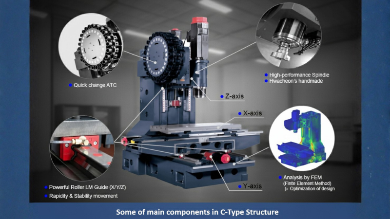
- Spindle
The spindle is the heart of the CNC milling machine. It’s a rotating shaft that holds and drives the cutting tool. Its cutting speed can range from a few hundred to over 20,000 RPM.
High-speed spindles are essential for aerospace and electronics involving fine tolerances and smooth finishes. Spindles run at 30,000 RPM in advanced aerospace machining.
- Tool Changer (ATC)
The Automatic Tool Changer (ATC) allows the machine to swap tools without manual intervention. It’s an essential prerequisite for complex parts requiring multiple operations.
Modern ATCs can hold 20 – 300 tools, depending on machine size. Automotive plants execute ATCs to switch between a mill drill, end mill, and reamer, cutting cycle times by 40%.
- Worktable
The worktable secures the workpiece and moves along the X and Y axes. It enables 3D machining by combining spindle movement along the Z-axis.
Precision fixturing on the worktable reduces vibration and improves accuracy. Stainless steel implants are clamped on CNC worktables to achieve tolerances within ±0.01 mm.
- Column and Saddle
The column provides vertical support, whereas the saddle allows controlled worktable movement. Together, they ensure rigidity and stability.
Heavy-duty columns in German CNC machines are designed to withstand cutting forces in automotive engine block production.
- Control Panel
The control panel is the operator’s interface, where commands are input and monitored. It interprets G-code and manages the versatile machine functions.
Modern CNC panels integrate touchscreens and IoT for remote monitoring. Smart control panels in Japan are linked to cloud systems, reducing programming errors by 25%.
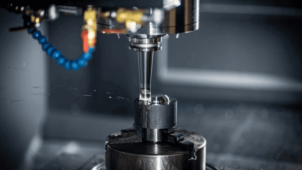
- Coolant System
The coolant system sprays liquid or air to reduce heat, extend tool life, and improve surface finish. Proper coolant use can extend tool life by 50%.
In aerospace machining, coolant prevents thermal expansion when cutting nickel alloys. It effectively ensures optimal dimensional accuracy.
- Linear Guides and Ball Screws
Linear guides and ball screws ensure smooth, precise movement of the machine’s axes. Ball screws convert rotary motion into linear motion with minimal friction.
High-precision ball screws achieve repeatability within ±0.005 mm. Regular lubrication of ball screws prevents backlash and maintains accuracy.
How CNC Milling Process Works: Step-by-Step Process

Step #01: From CAD to CAM
It begins with a CAD (Computer-Aided Design) model, where engineers design the part digitally. The model is then imported into CAM (Computer-Aided Manufacturing) software to generate toolpaths.
A toolpath refers to the exact routes the cutting tool will follow. Finally, the CAM system produces G-code, the machine-readable instructions that control spindle speed, feed rate, and tool movement.
Step #02: Machine Setup
- Fixturing/Clamping: The raw material (workpiece) is secured using vises, clamps, or custom fixtures to prevent movement.
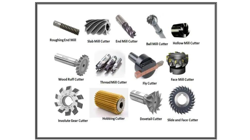
- Tool Selection: Engineers choose from a variety of tools—end mills for slots/pockets, drills for holes, and face mills for flat surfaces.
- Work Coordinate System: A “zero point” is set, defining the origin for all movements. Proper fixturing can improve surface finish by up to 25%.
Step #03: Material Removal
The spindle rotates cutting tools at high speeds (often 5,000 – 20,000 RPM). The tool follows precise toolpaths to remove material, shaping the workpiece into contours, slots, steps, and pockets.
Multi-axis CNC mills (5-axis) can reduce machining time by up to 60%, especially for complex geometries. Apple’s MacBook chassis is milled from a single aluminum block, achieving sleek designs at scale.
Step #04: In-Process Monitoring
- Coolant Supply: Keeps tools and workpieces cool, preventing thermal distortion.
- Vibration Control: Sensors detect chatter, which can damage tools and reduce accuracy.
- Tool Wear and Replacement: Automated systems track tool life and prompt replacements.
Regularly inspect cutting tools as worn tools can increase scrap rates by 15% – 20%.
Step #05: Final Output
- Inspection: Using coordinate measuring machines (CMMs) to verify tolerances.
- Finishing Operations: Processes like deburring, polishing, or coating may be applied.
- Delivery: The finished part is ready for assembly or distribution.
- 3-Axis CNC Milling Machine
It’s the most common type, offering precision machining along three linear axes (X, Y, and Z) –
- X-axis: left to right
- Y-axis: front to back
- Z-axis: up and down
It allows the machine to cut, drill, and shape parts with high accuracy. It’s considered the industry standard for machining flat surfaces, slots, holes, and simple 3D contours.
Features
- Spindle Speeds: Typically range from 3,000 to 20,000 RPM depending on material.
- Tool Changer: Automatic tool changers (ATC) can hold 10–40 tools for multi-step operations.
- Precision Movement: Ball screws and linear guides ensure tolerances within ±0.01 mm.
- Worktable Flexibility: Supports a wide range of materials – aluminum, steel, plastics, composites.
Advantages
- Cost-Effective: More affordable, accessible to small and medium manufacturers.
- Ease of Use: Ideal for beginners and widely taught in engineering programs.
- High Accuracy: Suitable for parts requiring tight tolerances.
- Versatility: Good for prototyping, small-batch production, and even mass production.
Limitations
- Restricted Geometry: Cannot efficiently machine complex curved surfaces or undercuts.
- Multiple Setups: Complex parts often require repositioning, increasing cycle time.
- Lower Productivity for Complex Parts: Machining time can be 30% – 50% longer.
- Surface Finish Constraints: Limited tool angles may affect finish quality on intricate geometries.
Applications
- Automotive: Engine housings, brackets, and transmission components.
- Aerospace: Flat panels, fixtures, and structural parts where tolerances are critical.
- Medical: Surgical instruments and orthopedic plates requiring precision for simpler curves.
- Consumer Electronics: Casings, heat sinks, and prototypes.
- Education and Training: Engineering schools use 3-axis mills to train students.
- 4-Axis CNC Milling Machine
It builds upon the standard 3-axis design (X, Y, Z) by adding a rotary axis (A-axis). The workpiece rotates around the X-axis, machining multiple sides without manual repositioning.
A 4-axis type bridges the gap between the basic 3-axis machining and the advanced 5-axis milling. The settings even offer greater flexibility and efficiency for complex parts.
Features
- Rotary Axis (A-axis): Workpiece rotation allows machining on different faces in one setup.
- CAD/CAM Integration: Advanced CAM creates toolpaths for simultaneous linear + rotary moves.
- Automatic Tool Changer (ATC): Supports multiple tools for milling machine operations.
- High Precision: Tolerances typically within ±0.01 mm, suitable for intricate geometries.
- Spindle Speeds: Angular milling ranges from 5,000–20,000 RPM depending on material.
- Worktable Flexibility: Suits metals, plastics, composites, and even wood for prototyping.
Advantages
- Reduced Setups: Eliminates the need to manually reposition the workpiece, saving time and reducing errors.
- Complex Geometry: Capable of machining cylindrical parts, curved surfaces, and features on multiple sides.
- Improved Efficiency: Cuts cycle times by up to 30–40% compared to 3-axis machines.
- Cost-Effective Alternative: More affordable than 5-axis machines while offering advanced capabilities.
Limitations
- Not Fully Versatile: Can’t handle extremely complexities of undercuts or freeform surfaces.
- Higher Cost than 3-Axis: More expensive to purchase and maintain compared to entry-level CNC mills.
- Programming Complexity: Requires advanced CAM programming skills, increasing training needs.
- Space Requirements: Larger footprint, making them less suitable for small workshops.
Applications
- Automotive: Engine components, transmission housings, and custom parts with multiple faces.
- Aerospace: Turbine blades, brackets, and structural components with precision on multiple sides.
- Medical Devices: Manufacturing implants and surgical tools with complex geometries.
- Consumer Electronics: Milling casings and enclosures with curved surfaces (smartphone housings).
- Industrial Equipment: Used in mold-making and tool production, especially in Asia-Pacific.
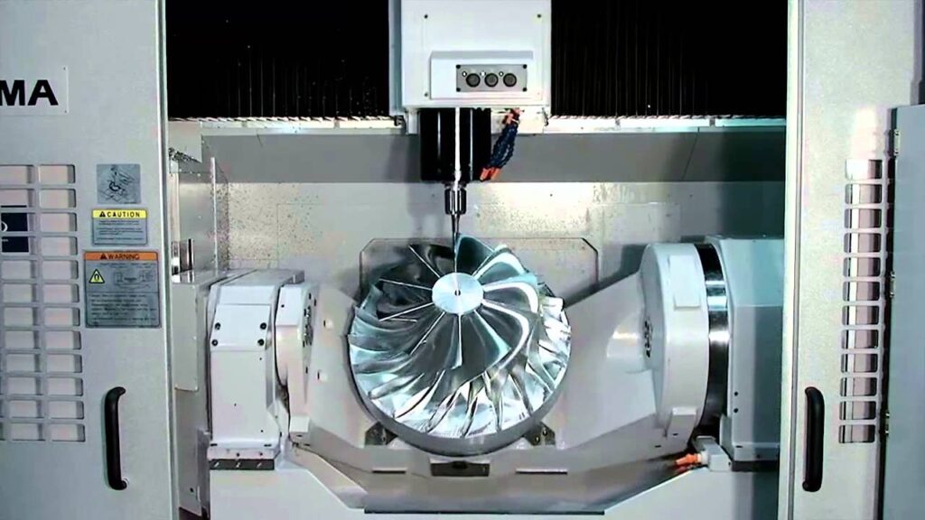
- 5-Axis CNC Milling Machine
It’s the most advanced type, capable of moving a cutting tool or workpiece along five different axes. Aside from the linear X, Y, and Z axes, it incorporates two rotary axes (commonly A and B or A and C).
The tool can approach the workpiece from virtually any direction. You can machine highly complex shapes in a single setup. 5-axis technology is considered the gold standard in high-end industries.
Features
- Simultaneous 5-Axis Movement: Machining of freeform surfaces, undercuts, and intricate geometries.
- High-Speed Spindles: Often exceeding 30,000 RPM for cutting tough materials like titanium and Inconel.
- Automatic Tool Changer (ATC): Holds 40 – 300 tools for multi-step operations.
- Precision: Achieves tolerances within ±0.005 mm, essential for aerospace and medical applications.
- Large Work Envelope: Suitable for both small intricate parts and large structural components.
Advantages
- Single Setup Efficiency: Complex parts can be machined in one go, reducing cycle times by up to 50%.
- Superior Accuracy: Eliminates repositioning errors, ensuring consistent quality.
- Complex Geometry Capability: Ideal for turbine blades, orthopedic implants, and automotive molds.
- Reduced Tool Wear: Optimized tool angles improve cutting efficiency and extend tool life.
Limitations
- High Cost: 5-axis machines can cost 2–3 times more, making them less accessible to SMEs.
- Programming Complexity: Requires advanced CAM software and skilled operators.
- Maintenance Demands: More moving parts mean higher maintenance requirements.
- Overkill for Simple Parts: Not for basic geometries that can be handled by 3- or 4-axis machines.
Applications
- Aerospace: Machining turbine blades, impellers, and structural components with complex curves.
- Medical Devices: Orthopedic implants, dental crowns, and surgical instruments with micron-level precision.
- Automotive: Creating molds, engine components, and custom high-performance parts.
- Energy Sector: Manufacturing components for wind turbines + oil and gas equipment.
- Consumer Electronics: Milling sleek, curved casings for smartphones, laptops, and wearables.
- Vertical CNC Milling Machine (VMC)
The spindle axis remains oriented vertically. The cutting tool moves up and down along the Z-axis. And the worktable moves in the X and Y axes.
VMCs are ideal for precision machining of flat surfaces, slots, holes, and complex contours. It’s among the most widely used, especially in small to medium manufacturing setups.
Features
- Vertical Spindle Orientation: Allows easy access to the workpiece and visibility during machining.
- Worktable Movement: Moves in X and Y directions, while the spindle enables vertical milling.
- Automatic Tool Changer (ATC): Holds 20–60 tools for multi-step operations.
- High-Speed Spindles: Typically range from 6,000–15,000 RPM, suitable for metals, plastics, and composites.
- Compact Design: Smaller footprint compared to horizontal mills, making them suitable for workshops.
- Precision Components: Ball screws and linear guides ensure tolerances within ±0.01 mm.
Advantages
- Cost-Effective: VMCs are generally cheaper than horizontal CNC mills, making them accessible to SMEs.
- Ease of Operation: Operators can easily monitor machining due to the vertical orientation.
- Versatility: Suitable for prototyping, small-batch production, and even mass production.
- High Accuracy: Capable of producing parts with tight tolerances.
Limitations
- Chip Evacuation Issues: Chips tend to accumulate on the workpiece due to gravity, requiring efficient coolant systems.
- Lower Material Removal Rate: Compared to horizontal mills, VMCs are less efficient for heavy-duty cutting.
- Limited Workpiece Size: Compact design restricts machining of very large parts.
- Surface Finish Constraints: May require secondary finishing for complex geometries.
Applications
- Automotive: Used for machining engine components, brackets, and transmission housings.
- Aerospace: Produces fixtures, panels, and precision components where tolerances are critical.
- Medical Devices: Ideal for surgical instruments and orthopedic implants.
- Consumer Electronics: Milling casings, heat sinks, and prototypes.
- Education and Training: Commonly used in engineering schools to train students.
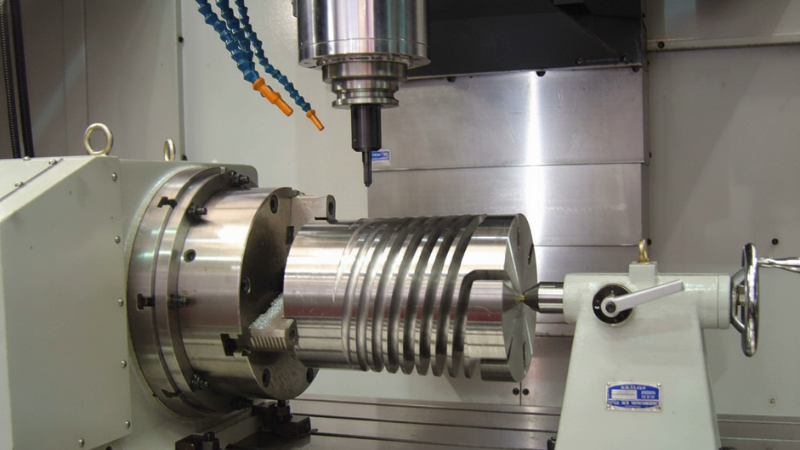
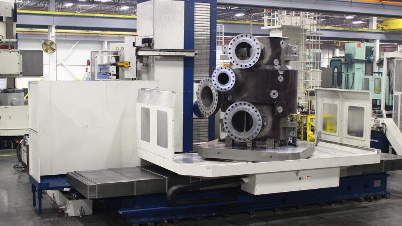
- Horizontal Milling Machine (HMC)
The spindle remains oriented horizontally. The cutting tool approaches the workpiece from the side. It enables better chip evacuation, higher material removal rates, and improved efficiency in machining.

Features
- Horizontal Spindle Orientation: Enables side-cutting and efficient chip removal.
- Rotary Pallet System: Many HMCs include automatic pallet changers, allowing continuous machining while operators load/unload parts.
- Large Work Envelope: Suitable for machining bulky components.
- Automatic Tool Changer (ATC): Can hold 40–300 tools for complex operations.
- High Material Removal Rate: Optimized for heavy-duty cutting of steel, titanium, and cast iron.
- Precision Components: Ball screws and linear guides ensure tolerances within ±0.01 mm.
Advantages
- Superior Productivity: HMCs can reduce cycle times by up to 50% compared to VMCs.
- Efficient Chip Evacuation: Gravity helps chips fall away, reducing tool wear and improving surface finish.
- Multi-Side Machining: Rotary tables allow machining on multiple sides in one setup.
- Durability: Built for heavy-duty operations, making them ideal for large-scale manufacturing.
Limitations
- Higher Cost: HMCs are significantly more expensive than VMCs, limiting accessibility for SMEs.
- Larger Footprint: Requires more floor space, making them less suitable for small workshops.
- Complex Setup: More advanced fixturing and programming are needed.
- Overkill for Simple Parts: Not cost-effective for basic machining tasks.
Applications
- Automotive: Engine blocks, transmission housings, and chassis components.
- Aerospace: Large structural parts, turbine housings, and landing gear components.
- Heavy Equipment: Construction machinery parts and industrial molds.
- Energy Sector: Components for wind turbines, oil rigs, and power generation equipment.
- Bridge-Type/Gantry Mill
It features a bridge-like structure spanning the worktable. The cutting head moves along the bridge, while the gantry or bridge itself may be stationary or movable depending on the design.
They’re engineered for large-scale machining, handling parts that are too big for conventional mills. Therefore, this particular type is commonly used for heavy-duty applications.

Features
- Bridge/Gantry Structure: Provides rigidity and stability for machining large parts.
- Large Work Envelope: Capable of handling workpieces several meters long and weighing multiple tons.
- Multi-Axis Capability: Often equipped with 3, 4, or 5-axis configurations for complex geometries.
- Automatic Tool Changer (ATC): Supports dozens of tools for multi-step operations.
- High-Power Spindles: Designed for cutting steel, titanium, and composites at high removal rates.
- Advanced Control Systems: Integrated CAD/CAM software for precise toolpath generation.
Advantages
- Machining Oversized Parts: Aerospace fuselage sections, ship components, and large molds.
- Reduced Setups: Large workpieces can be machined in one setup, improving efficiency.
- Superior Rigidity: Bridge design minimizes vibration, ensuring accuracy and surface quality.
- Productivity Gains: Gantry mills can reduce machining time by 30–40%.
Limitations
- High Cost: Gantry/bridge mills are among the most expensive CNC machines, often costing millions.
- Large Footprint: Require significant floor space and infrastructure.
- Complex Maintenance: More moving parts and larger structures increase maintenance demands.
- Overkill for Small Parts: Not cost-effective for workshops handling small or simple components.
Applications
- Aerospace: Machining wing spars, fuselage panels, and turbine housings.
- Automotive: Large molds for car body panels and chassis components.
- Shipbuilding: Cutting structural steel plates and large assemblies.
- Energy Sector: Producing parts for wind turbines, hydroelectric dams, and oil rigs.
- Heavy Equipment: Manufacturing molds and dies for construction machinery.
- Mini CNC Mills and Desktop System
The compact, computer-controlled milling is for small-scale machining, prototyping, and educational use. They’re lightweight, portable, and optimized for precision work on smaller parts.
Hobbyists, startups, research labs, and educational institutions can benefit from its affordability and ease of operation. Mini CNC systems are driving the democratization of manufacturing.

Features
- Compact Size: Fits on a desktop or small workshop bench.
- Spindle Speeds: Typically range from 5,000–15,000 RPM, suitable for plastics, wood, aluminum, and soft metals.
- Work Envelope: Smaller cutting area (often 200–500 mm in X/Y), ideal for prototypes and small parts.
- CAD/CAM Integration: Compatible with popular software like Fusion 360, SolidWorks, or Easel.
- Affordable Pricing: Entry-level systems can cost under $2,000, compared to industrial machines costing hundreds of thousands.
- Plug-and-Play Setup: Many desktop CNCs are designed for easy installation and beginner-friendly operation.
Advantages
- Accessibility: Affordable for hobbyists, students, and small businesses.
- Portability: Easy to move and install in small spaces.
- Learning Tool: Ideal for teaching CNC fundamentals in schools and universities.
- Rapid Prototyping: Enables startups to test product designs quickly without outsourcing.
Limitations
- Limited Workpiece Size: Cannot handle large or heavy parts.
- Lower Power: Not suitable for hard metals like titanium or hardened steel.
- Reduced Productivity: Slower material removal rates compared to industrial CNCs.
- Durability: Less robust than industrial machines, requiring careful maintenance.
- Accuracy Constraints: Tolerances are typically within ±0.05 mm, sufficient for prototypes.
Applications
- Education: Engineering schools and vocational institutes use mini CNCs to train students.
- Startups/Makerspaces: Prototyping consumer products, electronics casings, and custom parts.
- Jewelry/Art: Engraving, carving, and precision cutting of small decorative items.
- Medical Research: Labs use desktop CNCs for machining small experimental components.
Comparison Table: Different Types of Milling Machines
How to Choose the Best CNC Milling Machine for Your Needs?
- Part Geometry
Choose 5-axis if you need undercuts, compound angles, organic surfaces, or turbine-like geometry; 4-axis for indexed multi-face parts and cylindrical features; 3-axis for prismatic parts.
- Tolerance Target
For ±0.05 mm general precision, 3-axis VMC is sufficient. For ±0.01–0.02 mm precision, 4-axis/rigid VMC or HMC. ≤±0.01 mm on complex surfaces needs 5-axis with thermal stability and probing.
- Surface Finish
You may need low Ra finishes (cosmetic consumer casings, mold cavities). Prioritize high-speed spindles, rigid construction, and in-machine probing for finishing passes.
- Production Volume
VMC or 4-axis VMC offers flexibility and cost control for low – mid volume (1–5,000 units). HMC with pallet changers and tombstones reduces setups and cycle time suffice mid – high volume.
- Materials and Spindle Power
Aluminum/Plastics: High-speed spindles (12k–30k RPM), lighter cuts; VMCs or mini CNCs for early prototyping.
Steel/Stainless: Rigid frames, higher torque spindles (8k–12k RPM), flood coolant; VMC/HMC.
Titanium/Inconel: 5-axis or rigid HMC, strong torque, advanced coolant (through-spindle), and toolpath optimization.
Composites: Dust extraction, anti-abrasive tooling; gantry machines for large panels.
- Size, Rigidity, and Workspace
Part Envelope: Verify X/Y/Z travels exceed part size plus fixturing. Gantry if parts exceed typical VMC/HMC capacity.
Rigidity: Box ways or hybrid linear/box ways for heavy cuts (steel/titanium); linear guides for speed and light-to-medium cuts.
Footprint: HMCs and gantries need more space, power, and handling equipment than VMCs.
Common CNC Milling Operations
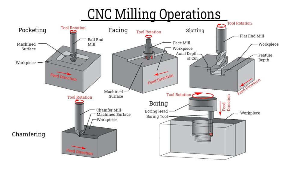
- Facing (Face Milling)
It’s the process of creating flat surfaces on the workpiece. The cutting tool removes a thin layer of material, producing a smooth, level surface.
Purpose: Facing establishes a reference surface or prepares the workpiece for further machining. Use face mills with multiple inserts for faster material removal and better surface finish.
- Contouring and Profiling
Contouring and profiling involve following 2D or 3D toolpaths. The machining operations cut shapes, curves, and complex geometries.
Purpose: They create external shapes or intricate profiles. Optimize toolpaths in CAM software to minimize tool wear and reduce cycle time.
- Slotting and Pocketing
Slotting and pocketing create internal cavities, channels, or recesses within the workpiece.
Purpose: They’re crucial for parts with internal features like slots for keys or pockets for components. Use high-speed machining strategies to reduce tool load and improve efficiency.
- Drilling, Boring, and Tapping
These operations produce holes and threaded features. Drilling creates round holes, boring enlarges or refines existing holes, and tapping cuts internal threads.
Use peck drilling cycles for deep holes to prevent tool breakage. Medical device manufacturers use CNC tapping to produce threaded implants with micron-level accuracy.
- Engraving in Plunge Milling or Plain Milling
Engraving adds text, logos, or markings directly onto the workpiece.
Purpose: Branding, identification, or functional markings. Use small-diameter end mills or laser-assisted engraving for fine details.
- Surface Finishing Passes
Surface finishing passes refine the workpiece to achieve required Ra roughness values or cosmetic finishes.
Purpose: Improves aesthetics and ensures functional smoothness. Use climb milling for better surface finish and reduced tool wear.
Comparison Table: CNC Milling Operations (Excluding Slab Milling or Peripheral Milling)
CNC Milling Materials: What Materials can be Milled?
CNC milling can process lots of different materials. The range covers from lightweight aluminum to high-performance plastics.
- Aluminum (Most Common)
Excellent machinability, lightweight, corrosion-resistant. Accounts for over 50% of CNC milled parts.
Applications: Aerospace components, automotive housings, consumer electronics.
- Steel and Stainless Steel
Strong, durable, but harder to machine than aluminum. Stainless steel resists corrosion, making it vital for medical and food industries.
Example: Surgical instruments and automotive engine parts.
- Brass
Soft, easy to machine, excellent for precision parts. Produces smooth finishes without much effort, reducing secondary polishing.
Applications: Plumbing fittings, electrical connectors, decorative items.
- Copper
High thermal and electrical conductivity. Tends to gum up tools; requires sharp cutters and coolant.
Applications: Heat exchangers, electrical components.
- Titanium
High strength-to-weight ratio, biocompatible. Difficult to cut; generates heat, requiring advanced cooling systems.
Example: Widely used in aerospace and medical implants.
- Magnesium Alloys
Extremely lightweight, good machinability. Flammable chips; requires careful handling and coolant.
Applications: Automotive and aerospace lightweight structures.
- ABS (Acrylonitrile Butadiene Styrene)
Easy to machine, affordable, widely used in prototyping.
Applications: Consumer product prototypes, enclosures.
- POM (Polyoxymethylene, also called Delrin)
High stiffness, low friction. Excellent dimensional stability during machining.
Applications: Gears, bearings, automotive components.
- Nylon
Tough, wear-resistant, but absorbs moisture. Dimensional changes due to humidity.
Applications: Bushings, mechanical parts.
- Polycarbonate (PC)
Transparent, impact-resistant. Requires sharp tools to avoid cracking.
Applications: Safety equipment, housings, lenses.
- PEEK (Polyether Ether Ketone)
High-performance engineering plastic, resistant to chemicals and heat. Expensive, requires specialized tooling.
Example: Aerospace and medical implants where tolerances are critical.
- Composites (Carbon Fiber, Fiberglass)
Lightweight, strong, but abrasive on tools. Diamond-coated tools extend tool life.
Applications: Aerospace panels, sporting goods.
- Wood (for Prototyping)
Easy to cut, inexpensive, ideal for mock-ups. Not suitable for industrial-grade precision.
Applications: Furniture prototypes, design models.
Design for Manufacturability (DFM) Guide for CNC Milling
- Choose the Right Tolerances
Avoid specifying unnecessarily tight tolerances (±0.01 mm) unless functionally required. Automotive brackets often only need ±0.1 mm tolerance, while aerospace turbine blades require ±0.01 mm.
- Avoid Deep Narrow Cavities
Cavities deeper than 4× the tool diameter are difficult to machine, causing tool deflection and wear. Mold-making in Japan uses stepped cavity designs instead of deep narrow slots to reduce tool stress.
- Use Standard Hole Sizes
Stick to standard drill sizes (metric or imperial) to avoid custom tooling. Electronics housings in Asia-Pacific use standard M3/M4 threaded holes for screws, ensuring compatibility and reducing costs.
- Add Fillets Inside Corners
Internal corners should have fillets (radius) to match tool geometry. Sharp corners require extra passes and increase machining time. Apple’s laptop chassis uses rounded internal corners for both aesthetics and manufacturability.
- Keep Wall Thickness Reasonable
Thin walls (<1 mm in metals) can cause chatter, deformation, or breakage. Minimum thickness is 1 mm for metals and 1.5 mm for plastics. German automotive housings maintain 2–3 mm walls for durability.
- Optimize Material Selection
Match material to mechanical needs and cost; don’t over-specify exotic alloys unless necessary. Aluminum parts accounts for over 50% of CNC milled parts due to its machinability and affordability.

When CNC Milling is the Right Choice
- Low to Mid-Volume Production
CNC milling excels in small to medium batch runs where flexibility and precision matter. It’s cost-effective up to 1,000–5,000 parts, after which casting or stamping becomes cheaper. For startups, CNC milling bridges the gap between prototyping and early production without heavy tooling costs.
- Tight Tolerances
CNC mills achieve tolerances as tight as ±0.005–0.01 mm, essential for aerospace and medical industries. Orthopedic implants in the U.S. require micron-level precision, achievable only with CNC milling.
- Prototyping with Fast Turnaround
CNC milling offers rapid prototyping directly from CAD models. CAD-to-CNC workflows can reduce design-to-production time by up to 40% compared to traditional methods.
- Parts Requiring Precision Features
CNC milling is ideal for slots, pockets, threads, and complex contours. Aerospace turbine blade fixtures require precision features that only multi-axis CNC milling can deliver.
CNC Milling vs Other Manufacturing Alternatives
FAQs
What materials can be CNC milled?
CNC milling works with metals (aluminum, steel, titanium, brass, copper), plastics (ABS, POM, nylon, PEEK), composites, and even wood for prototyping.
What are the limitations of CNC milling?
Limitations include higher upfront costs, programming complexity, and inefficiency for extremely high-volume production compared to die casting or stamping.
How accurate is CNC milling?
Modern CNC mills achieve tolerances of ±0.005–0.01 mm. It makes the process suitable for aerospace and medical applications requiring micron-level precision.
What software is used in CNC milling?
CNC milling relies on CAD for modeling and CAM for toolpath generation. Popular software includes Fusion 360, SolidWorks, and Mastercam.
Can CNC milling be used for prototyping?
Yes. CNC milling is ideal for rapid prototyping. It offers fast turnaround and functional prototypes with production-grade accuracy.
Conclusion
A CNC milling machine covers an integral part of modern precision manufacturing. It transforms raw materials into highly accurate, repeatable parts. And each milling machine type serves a unique role in shaping particular segments of high-end industries.
Material Machining in Its Finest at HONJENNY
Honjenny promises to keep a perfect balance of design, execution, and quality. 30+ years of expertise has established us as a top brand in the industry. Contact us for consultation for manufacturing details.
