
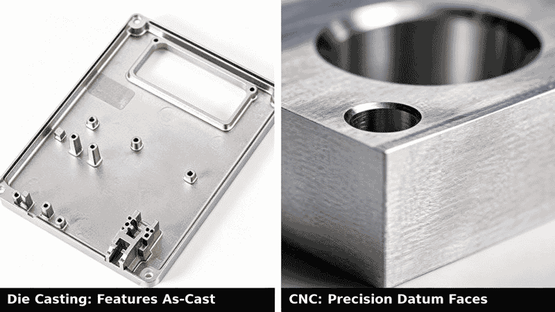
An optical transceiver housing may look simple, but a few hundredths of a millimeter can decide whether the PCB sits correctly, the covers close evenly, or the heat sink makes full contact. Designers sometimes respond by tightening the entire drawing and machining every important feature. That can raise cost and lead time, and repeated clamping may even add distortion. A better approach is to choose tolerances by function and proven process capability. Here is how we divide optical transceiver housing tolerances between die casting and CNC, supported by two production cases.
Quick Answer: Die Casting or CNC for Tight Tolerances?
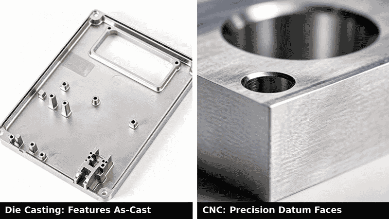
Die casting is usually suitable for thin walls, ribs, clips, slots, bosses, and repeated features that the die can form consistently. CNC is more suitable for precision datum faces, optical interfaces, locating surfaces, and large flat areas that may change shape during cooling.
The dividing line is not simply “loose equals die casting” and “tight equals CNC.” A small ±0.02 mm slot may be stable as-cast when the tool and process support it. A large surface with 0.05 mm flatness may need milling because warpage, not nominal size, is the problem.
The real question is whether a feature can be formed and measured consistently in production, or whether machining gives a more reliable functional result.
Why Tolerance Planning Matters in an Optical Transceiver Housing
Tolerance decisions influence tool design, parting lines, fixtures, assembly fit, thermal contact, EMI grounding, yield, and delivery time.
A 0.03 mm sidewall deviation may have no effect, while the same deviation at a PCB locator or optical interface can interrupt assembly. A surface may also meet its thickness requirement but fail flatness and make poor heat-sink contact.
Industry standards also separate standard and precision tolerances. The NADCA Product Specification Standards cover tolerances, datums, and geometric dimensioning. The International Zinc Association design guidance explains that accuracy depends on feature size, die construction, and whether a dimension crosses moving and fixed die elements.
An effective drawing tells the supplier where precision creates functional value. It does not make every surface equally important.
Which Housing Features Can Usually Remain As-Cast?
This is a starting point, not a universal standard. Capability depends on alloy, geometry, tool condition, and measurement method.
Zinc alloys are useful for thin walls and fine details. NADCA’s zinc die-casting overview notes their ability to produce complex shapes with tight tolerances and accept plating or finishing. This does not mean every zinc feature automatically holds ±0.02 mm. The feature, tool, and process must be planned together.
A Tight Functional Tolerance Does Not Always Need CNC
In one ZAMAK 3 QSFP28 100G project, a grounding spring clip slot inside the sidewall was only 0.8 to 1.2 mm wide. Its width and center position had to remain within ±0.02 mm.
Machining required a small cutter to side-mill a narrow, shallow slot. Difficult alignment, cutter chatter, and burrs could add cost without improving stability.
We treated it as a precision as-cast feature. Its die insert was cut by slow-speed wire EDM and controlled within ±0.01 mm. For this housing and tool, observed shrinkage of about 0.4% was used for compensation. This project-specific value should not be copied to another part without trials.
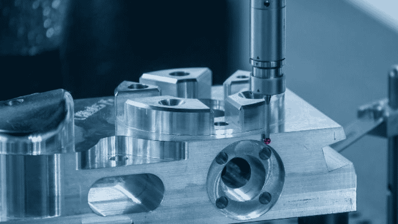
After the shot parameters and die temperature were stabilized, CMM sampling showed that the slot width and center distance stayed within the ±0.02 mm requirement. The process achieved a Cpk of at least 1.33.
Cpk indicates how a stable process fits within its limits. NIST’s process capability guidance explains that such analysis is meaningful only when the process is stable and in statistical control, not from one “good part.”
A standard grounding spring was also inserted and removed 100 times. Contact resistance remained within the customer’s requirement.
The lesson is simple: a critical dimension may still be die cast when the tool, process data, and functional tests support it.
When CNC Machining Is the Safer Choice
CNC becomes valuable when casting variation directly affects function. Examples include:
- Optical mating faces that must maintain a precise relationship to internal locators
- PCB locating holes that need tighter position control than the as-cast process can demonstrate
- Large thermal contact faces with demanding flatness requirements
- Sealing, locating, or assembly surfaces affected by parting-line mismatch or flash
- Features that need one consistent datum across several operations
Machining should create reliable functional references, not turn the casting into a fully machined block. Related features should use one consistent datum and, where possible, one setup. Otherwise, fixtures may reproduce casting variation or distort a thin housing.
Case Study: When a 0.05 mm Flatness Requirement Needed Milling
In an ADC12 QSFP-DD 400G base project, the heat-sink mounting face required 0.05 mm flatness. The customer initially requested an as-cast surface to avoid milling.
Trial parts measured 0.09 to 0.13 mm flatness, with the worst exceeding the requirement by 0.08 mm. Incomplete heat-sink contact raised thermal resistance, and full-load module temperature was 6°C above target.
The base had a large aspect ratio and uneven walls. Cooling stress left a slight crown at the center, while the parting line at the bottom edge introduced minor mismatch and flash. Die casting could not hold the requirement consistently across the full area.
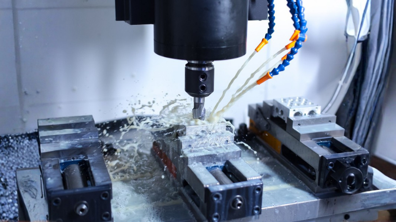
We added 0.3 mm machining allowance, located the part from two internal posts, and finish-milled the face in one setup.
Flatness then remained within 0.03 mm. Thermal-resistance defects fell from 24% to below 0.6%, and yield rose from 73% to 95.2%. One milling operation cost less than continued scrap and rework.
Removing CNC is not a saving when the as-cast surface creates unstable thermal contact.
Case Study: Over-Tolerancing Increased Cost and Reduced Yield
The opposite problem occurred on a ZAMAK 3 QSFP28 100G upper and lower housing set. The original drawing applied ±0.02 mm to almost every dimension, including the outside sidewalls, non-mating internal ribs, non-mating portions of screw bosses, and cosmetic grooves. All of these areas were specified for CNC machining.
Our DFM review separated the dimensions into three groups:
- CNC-controlled functional features: the optical port mating face, PCB locating holes, and the locating faces of the upper-to-lower housing step.
- Precision as-cast functional features: the grounding spring clip slot described earlier, which retained ±0.02 mm.
- Non-critical as-cast features: external sidewalls, non-load-bearing ribs, non-mating boss sections, and decorative grooves. For this project, these were released to a normal casting tolerance of ±0.05 mm.
This did not mean that ±0.05 mm is appropriate for every zinc housing dimension. It was acceptable here because those features did not control PCB location, optical alignment, cover fit, or grounding contact.
The revised plan reduced CNC operations from seven to two. Machining time fell from 11 minutes to 3 minutes per part, and total unit cost decreased by 27%. With fewer setups, there was also less clamping-related deformation. Production yield increased from 81% to 96.8%, and batch lead time fell from six days to three days.
The main saving did not come from relaxing quality. It came from applying precision only where the module used it.
How to Allocate Optical Transceiver Housing Tolerances
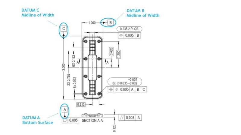
A practical tolerance review can follow seven questions.
1. What Function Does the Feature Control?
Connect each tight tolerance to PCB position, optical alignment, cover assembly, EMI contact, thermal transfer, sealing, or another measurable function. If no function changes, the tolerance may be tighter than necessary.
2. Is the Requirement About Size, Position, or Form?
A ±0.02 mm width tolerance and a 0.05 mm flatness requirement describe different problems. One controls feature size, while the other controls an entire surface. Do not assume the same manufacturing process will solve both.
3. Where Is the Functional Datum?
Define how the housing is located during assembly and inspection. Then use the same logic for tooling and CNC fixtures. A clear datum structure prevents suppliers from measuring a correct feature from the wrong reference.
4. How Is the Feature Formed in the Die?
Review whether it sits in one die half, crosses the parting line, depends on a slide, or requires a replaceable insert. Features formed by several moving tool elements usually carry more accumulated variation.
5. Is Warpage More Important Than Nominal Size?
Large, thin, or uneven sections can change shape after ejection. For thermal faces and long mating edges, evaluate flatness, profile, and assembly gap instead of looking only at length and width.
6. What Does Production Data Show?
Use CMM results across multiple cavities, shifts, and batches. A capable process needs controlled settings, maintained tooling, a defined measurement method, and enough data to show repeatability.
7. What Happens After Plating or Coating?
Nickel plating, chrome plating, painting, or conductive treatments add thickness and can affect small slots and mating areas. State whether drawing dimensions apply before or after finishing, and identify masked or contact-critical surfaces.
What to Include in Your RFQ
To receive a useful DFM response, send more than a 3D model. Include:
- Alloy preference and whether an alternative material can be evaluated
- Annual volume, prototype quantity, and expected production life
- A drawing with critical characteristics clearly marked
- Datum scheme and inspection method
- Mating parts or interface specifications
- Flatness, position, contact resistance, and thermal test requirements
- Surface finish, coating thickness, and masked areas
- Assembly samples or gauges when available
Ask the supplier to identify which features will be as-cast, which will be machined, and what evidence supports each decision. For unfamiliar designs, a tool-trial and capability plan is more useful than a broad promise about one tolerance number.
Conclusion
The best tolerance strategy for an optical transceiver housing is usually a controlled combination of die casting and CNC machining. Die casting can produce thin walls, fine slots, ribs, and even selected ±0.02 mm functional features when the tool and process demonstrate capability. CNC should be reserved for interfaces and surfaces where casting variation, warpage, or parting-line effects create a functional risk.
Before releasing the mold, classify every tight tolerance by function, datum, forming method, and validation plan. This short review can remove unnecessary machining while protecting the dimensions that affect optical alignment, grounding, assembly, and heat transfer.
Reduce CNC Costs Without Compromising Critical Tolerances
Honjenny provides DFM analysis, precision die casting, CNC machining, and CMM inspection for optical transceiver housings. Send us your drawings and tolerance requirements, and our engineers will help determine which dimensions can be achieved by die casting and which require CNC machining. Request a DFM review and quote for your project.