
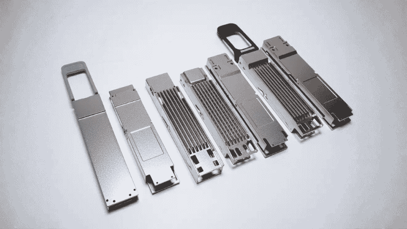
An optical transceiver housing may be small, but a minor design error can cause poor fit, visible sink marks, or unstable assembly in mass production. Zinc die casting is well suited to compact housings because it can form thin walls, locating features, ribs, and latches in one production cycle. However, the drawing still needs to account for metal flow, ejection, cooling, machining, and plating. Our work on QSFP28 and QSFP-DD housings shows that early DFM review can prevent problems that are expensive to correct after tooling. This guide explains the main design choices in practical terms and shows what to check before requesting a quote.
What Is an Optical Transceiver Housing?
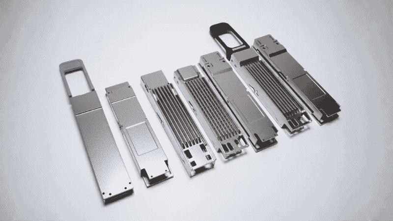
An optical transceiver housing is the metal shell around the PCB, optical components, and related internal parts of a pluggable transceiver. Depending on the design, the housing may also locate the PCB, support a latch, create contact with the cage, and help transfer heat away from internal components.
The housing should not be confused with the transceiver cage. The housing travels with the module when it is inserted or removed, while the cage is mounted on the host equipment and is commonly made from stamped sheet metal.
Common housing formats include SFP, SFP+, QSFP28, QSFP-DD, and OSFP. Each has a defined mechanical envelope and interface, so the first design step is to identify the exact format and specification revision. The SNIA SFF specifications, for example, include documents covering SFP+ modules and cages as well as QSFP module solutions. QSFP-DD projects should follow the mechanical and thermal requirements in the applicable QSFP-DD MSA hardware specification.
These specifications define the interface, but they do not automatically make every internal rib, boss, or wall suitable for die casting. That is where design for manufacturing, or DFM, begins.
Why Use Zinc Die Casting for an Optical Transceiver Housing?
Zinc alloys fill small and detailed cavities well. This makes hot-chamber zinc die casting useful when a housing combines thin walls with locating posts, latch features, ribs, slots, and cosmetic surfaces.
Once the tool and process are stable, many features can be produced near their final shape, reducing secondary operations at production volume.
Zinc is not automatically the best material for every transceiver. It is denser than aluminum, and aluminum may be more suitable when low weight or higher bulk thermal conductivity is the main priority. A zinc housing should therefore be selected because its precision, castability, strength, finishing, and production economics match the product, not simply because zinc has been used on an earlier model.
ZAMAK 3 or ZAMAK 5?
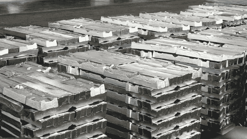
ZAMAK 3 is a practical starting point for many precision housings because it combines castability, dimensional stability, and finishing performance. ZAMAK 5 adds copper and is slightly stronger and harder, although it has lower ductility.
The International Zinc Association alloy guide notes that Alloy 5 is readily plated, finished, and machined like Alloy 3. Choose between them according to latch load, screw or crimp features, wall design, finish, and operating conditions.
Key DFM Rules for Zinc Die-Cast Housings
A good DFM review separates dimensions that control function from features that only need to be manufacturable.
Do Not Make Every Wall 0.5 mm
A 0.5 mm wall may be achievable in a small zinc casting, but it should not become the default value for the entire housing. The practical limit changes with the distance from the gate, flow path, surrounding features, and required rigidity.
The zinc die casting design guide explains that minimum practical wall thickness increases with distance from the ingate. It also recommends reasonably uniform sections because abrupt thick areas can create shrinkage porosity.
Pay particular attention to PCB locating posts, screw bosses, ribs, and latch supports. A thick feature attached to a thin wall cools more slowly and may cause internal shrinkage or a visible depression on the opposite surface.
Provide Enough Draft for Release
Draft is the slight angle that lets a casting leave the die without scraping or sticking. Too little draft may damage an internal wall or distort the part during ejection.
The zinc design guide lists a normal minimum of 1 degree for internal surfaces and 0.5 degree for external surfaces. Treat these as starting points because depth, texture, and ejection direction also matter.
Keep Parting Lines Away From Functional Surfaces
The parting line is where the two main die halves meet. A small amount of flash can form there, so placing it on a sealing datum, grounding contact, or latch interface can turn a minor casting condition into an assembly failure.
Move the parting line when possible. Otherwise, define how flash will be trimmed and the surface inspected.
Use Ribs and Plan Tool Features Early
Rounded, well-distributed ribs improve stiffness without creating a thick solid wall. Avoid joining several ribs, a boss, and an outer wall at one heavy point. Reduce the boss root, add a radius, or core out excess material instead.
Gate and overflow locations affect how metal reaches thin sections. Ejector pins should stay away from contact surfaces, while side holes and undercuts may require slides that add tooling cost and dimensional variation.
Factory DFM Case: Preventing Problems in a QSFP28 Housing
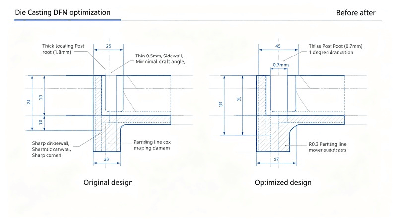
We reviewed a QSFP28 lower housing made from ZAMAK 3 before tool release. The PCB locating post had a 1.8 mm thick root next to a 0.5 mm sidewall, creating a section ratio above 3:1.
The inner wall had only 0.3 degree of draft, and the proposed parting line ran directly across the mating datum between the upper and lower covers. If released as drawn, the design carried four clear risks: shrinkage at the post, a sink mark on the opposite surface, distortion from uneven cooling, and flash on the mating surface.
We reduced the post root from 1.8 mm to 0.7 mm and added an R0.3 mm transition. This brought the local thickness ratio within 1.4:1. We also increased the internal draft to 1 degree and moved the parting line 0.2 mm toward the outside of the housing, away from the mating datum.
The first tool trial passed dimensional and appearance checks, with flatness within 0.04 mm. Our earlier DFM assessment had projected about 0.14 mm of distortion and roughly 68% yield for the original design. These were risk estimates because that version was not released. After optimization, actual mass-production yield reached 98.2%, with no observed sink marks or ejection scratches.
The lesson is not that every locating post should be 0.7 mm. It is that a small internal feature must be reviewed together with the wall around it, the cooling pattern, and the surface on the opposite side.
Which Features Should Be Cast and Which Should Be Machined?
Machining every important-looking surface increases cost without guaranteeing better assembly. However, a tight as-cast tolerance may also be unstable if the datum, die half, and slides are ignored.
Use the table below as a starting point, then confirm the final plan through drawing review.
Identify the functional datums, such as the bottom mounting plane, PCB locating features, and cover-latch interfaces. Then check the full tolerance chain because several moderate deviations can combine into a visible cover gap.
For tighter features, secondary CNC machining can bridge the gap. Machine only functional surfaces and leave enough stock for cleanup without cutting deeply into the casting.
Surface Finishing, EMI, and Contact Areas
Nickel plating, chromium plating, passivation, painting, and other finishes can protect or modify a zinc housing. The correct finish depends on corrosion exposure, wear, appearance, electrical contact, and customer specifications.
The International Zinc Association confirms that common zinc die casting alloys can be polished and plated. Its polishing and plating guidance lists nickel and chromium among available finishes and notes that unprotected polished zinc tarnishes over time.
Finishing must be included in the tolerance plan. A coating changes the final size of slots, holes, latch surfaces, and cover interfaces, even when the change is small.
A metal housing alone does not guarantee an EMI shielding result. Openings, seams, coatings, grounding paths, and contact pressure also matter, so EMI and thermal performance should be tested on the assembled module.
Factory Production Case: Fixing an Uneven QSFP-DD Cover Gap
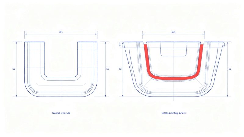
During early production of a QSFP-DD zinc housing, the customer found an uneven gap after the upper and lower covers were latched together. The largest gap on one side reached 0.13 mm, above the 0.05 mm requirement, and some latches did not fully engage. The sampled defect rate was 17%.
CMM inspection showed that the two open sidewalls were spreading outward. Warpage measured 0.07 to 0.11 mm around the latch interfaces and bottom mounting datum.
Comparisons across batches and parameter sets showed that the casting left the die before it had cooled enough. Residual stress then opened the long, thin sidewalls after ejection.
The correction combined tooling and process changes:
- Added 0.06 mm of inward compensation to the die sidewalls.
- Extended in-die cooling time by two seconds.
- Reduced pressure in the final injection stage.
- Placed each hot casting in a sizing fixture while it completed cooling.
After these changes, sidewall warpage remained below 0.03 mm and assembly-gap defects fell from 17% to less than 0.4%. The separate manual rework operation was no longer needed.
This is why one linear dimension was not enough to explain the failure. Wall profile, flatness, cooling, and the relationship between mating parts all contributed.
How Should an Optical Transceiver Housing Be Inspected?

Inspection should follow the housing function rather than a generic checklist.
Dimensional and Assembly Checks
Use CMM or gauges to measure datums, wall profile, flatness, locating features, and latch positions. A fixture or actual mating parts can confirm cover engagement and PCB location.
Casting Quality Checks
Visual inspection can find flash, incomplete fill, scratches, and sink marks. Add X-ray for higher-risk regions or agreed sampling rather than treating it as the default for every feature.
Finish Checks
Verify coating appearance, thickness, adhesion, and coverage according to the drawing. Pay extra attention to small slots, internal corners, and electrical contact areas where burrs or residues can affect fit.
First article inspection should record critical dimensions and measurement methods. Production checks can then focus on wall spread, cover gap, latch position, and coating buildup.
What Should You Include in an RFQ?
A clear RFQ lets the die caster review risk before quoting. Include:
- 3D CAD file, preferably STEP or IGES.
- 2D drawing with datums, critical tolerances, and finish notes.
- Transceiver format and applicable MSA or SFF revision.
- Requested alloy, or permission for the supplier to recommend one.
- Plating or coating type, thickness, and masked contact areas.
- Prototype quantity, first production order, and estimated annual volume.
- Required inspection reports and assembly or functional tests.
- Photos or samples of mating parts when the tolerance chain depends on them.
If the design is still developing, mark which dimensions are fixed by the interface and which can change. This gives the toolmaker room to improve filling, ejection, and machining access.
Conclusion
A reliable optical transceiver housing starts with three decisions: choose the material for the actual product requirements, adapt the geometry to zinc die casting, and control critical interfaces through a realistic casting and machining plan. Early review of wall transitions, draft, parting lines, datums, cooling, and finish thickness can prevent tooling changes and recurring assembly problems later.
The next practical step is to identify the dimensions that directly control PCB location, cover fit, latching, grounding, and insertion. These features should drive the DFM review and inspection plan.
Get DFM Support for Your Optical Transceiver Housing
Honjenny provides zinc die casting, in-house die cast tooling and DFM, CNC machining, surface finishing, assembly, and dimensional inspection for custom precision housings. Send us your 3D model, 2D drawing, transceiver format, finish requirements, and expected production volume to request a DFM review and quotation.